The foundation is the foundation of the building. And it is difficult to disagree with this axiom, because it is he who holds and evenly distributes the loads on the ground, ensures the stability and durability of the structure. But concrete is known to be quite tough material. To give the belt structure plasticity and ability to resist different types loads, the so-called reinforcement is used.
What is reinforcement for?
Simplified, a strip-type foundation is a closed loop of concrete under all the main walls of the structure along the perimeter. This is one of the most popular types of frames, because it is easy to build, it can withstand significant loads and allows you to additionally equip an operated basement. The disadvantages are the high consumption of building materials, the need to use special equipment (concrete pumps, cranes).
The tape type of foundation is being erected for buildings made of heavy piece materials (brick, blocks, stone) and houses with monolithic or prefabricated ceilings of a large mass. This type of foundation is optimal on heterogeneous soils, where there is a risk of uneven subsidence.
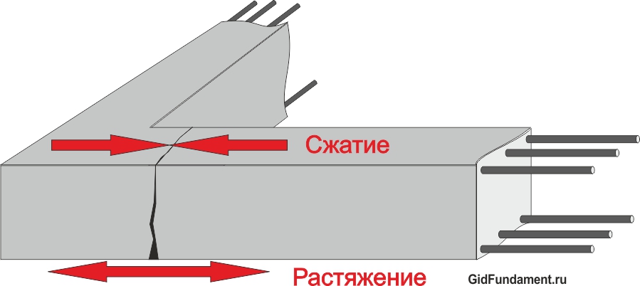
Foundation deformation diagram
The concrete structure can withstand two types of loads:
- Compression - the weight of the building and its contents (furniture, decoration, etc.).
- Stretching is influenced by frost heaving forces. Wet soil, freezing, expands and compresses the skeleton, pushing it up.
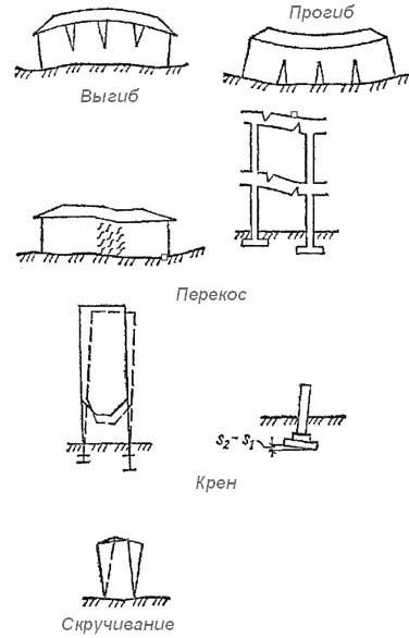
Obviously, these loads are uneven. So that the tape can resist deformations and, accordingly, cracks, breaks, the strip foundation is reinforced. In practice, this means the formation of a single metal frame inside the concrete framework. According to the rules, it should be located closer to the foundation edges, that is, in the zones of maximum compression-tension.
What materials are used for reinforcement
Even if the reinforcement of the strip type of foundation is conceived with your own hands, you need to choose the right components. The required materials include:
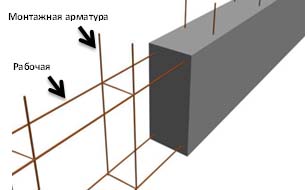
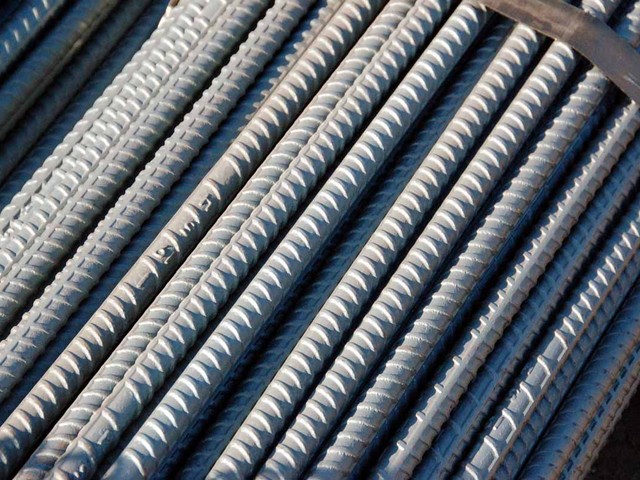
Rebar types
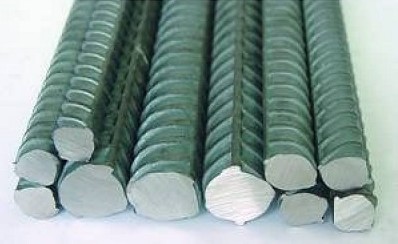
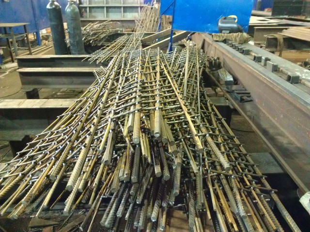
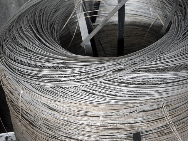
1. Steel or composite rebar - rods made of metal or fiberglass. They are sold in coils of 50-100 m or cut rolled metal with a length of 6-12 m. Smooth rods with a cross section of up to 10 mm are called assembly ones and are used for the vertical and transverse part of the frame. Corrugated rods with a diameter of 12-80 mm are designated as working ones. The upper and lower longitudinal parts of the "skeleton" are knitted from them.
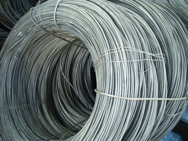
2. Steel wire for tying or tie straps. Less often welding is used (metal must be marked "C")
3. Clamping tool or special crochet hook, hacksaw for metal and the like.
The metal frame is the most popular among builders, its effectiveness and reliability has been proven over time. Foundation reinforcement fiberglass reinforcement used for those buildings that have special requirements for the level of radio interference, non-magnetic, chemical resistance. However, due to the fact that the composite does not stretch well when bending, that is, it actually does not perform one of the main functions, it is rarely used in private housing construction.
In no case should plastic bottles, metal corners or pipes, a coarse mesh netting, iron cables and other similar materials be used as the reinforcing cage of the foundation tape. This is not a skeleton, but foreign inclusions that will only harm the concrete base. The result is sad - the foundation will not withstand the design loads, damage to both the bearing base and the walls, floors, roof and other building elements is inevitable.
Calculation of reinforcement for strip foundations
It is not difficult to calculate the amount of material for reinforcement. Most often, a two- or three-row mesh frame is used. The step between vertical sections is 40-80 cm, between horizontally located levels - about 30-60 cm.That is, a deep foundation with a height of more than 90 cm requires 3-4 longitudinal tiers, for a skeleton less than 0.9 m deep, two are enough. Let's take an example:
- parameters of the concrete base (HxW) - 60x30 cm,
- building perimeter - 5x5 m,
- grid step - 50 cm,
Obviously, a two-tiered mesh will be needed. Working reinforcement for 4 longitudinal lines of 20 m each will require 80 linear meters. m, mounting vertical, taking into account an offset from the surface of 5 cm - 1.4 m * 51 (number of intersections) \u003d 71.4 m. Sellers recommend taking steel with a margin of at least 10%, so about 170 linear meters will be released in total. m fittings. Don't forget about the bundle. For each intersection, you get about 30 cm of wire. Joints in the section - 4 pcs, so with a margin of about 70 running. m. knitting metal.
How to independently reinforce a strip foundation
Reinforced concrete construction does not tolerate neglect. Before use, the fittings must be checked, cleaned from dirt and rust. Builders often neglect this step, although it is known that foreign inclusions impair the quality characteristics of the concrete frame.

The strip foundation reinforcement scheme is simple, but laborious:
- A 5 cm thick concrete “sole” is poured onto the sand-crushed stone “pillow”. It will protect the metal from corrosion and premature destruction. Sometimes, in order to save money, pieces of brick or stones are placed under the frame.
- Formwork is being placed.
- The required number of transverse mounting rods is laid on the concrete layer with an interval of no more than 80 cm.
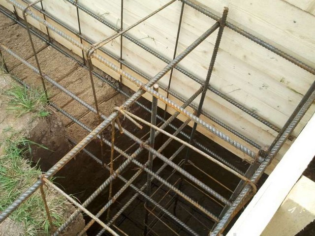
- Corrugated rods are superimposed on top in the longitudinal direction in two rows. The intersections are linked. It turns out the lower level of the reinforcing cage.
- In the joints, smooth steel of a given length is vertically mounted. Compliance with the geometry of the 90 ° corners is mandatory.
- The upper tier of the transverse mounting rods is tied to them. It turns out a frame, the overlap of the ends of which should be at least 20 cm.
- The upper longitudinal tier of the reinforcement "skeleton" is laid and fastened with knitting wire or clamps.
- With the help of spacers, the finished frame is rigidly fixed relative to the formwork. The gap between them should be at least 3-5 cm.
- The bundles are checked again, all excess material and debris are removed.
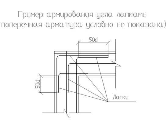
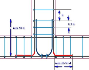
Reinforcement of the corner of the strip foundation is a headache for most specialists. This is where the so-called concentrated tension is formed. Therefore, special techniques are used - U- or L-shaped reinforcements created using clamps.
Schematically it looks like this:
For corners:
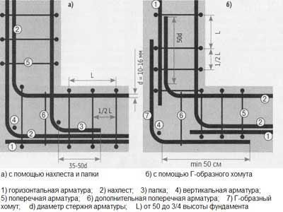
For crosshairs:
For mating angles less than 160 ° with L-shaped reinforcement:
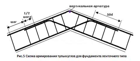
At the corner anchoring points, the clamps are mounted twice as often as in the rest of the strip foundation. It is these methods of corner reinforcement that create a rigid connection between the structural elements, allowing the loads to be evenly distributed.
Thus, the cost of materials is no more than 5% of the cost of erecting a reinforcing cage. Of course, saving on materials in this case is the last thing.
Over the entire period of its existence, mankind has accumulated vast experience in construction. The basis, the base of any building is a solid and reliable foundation. Today, the most common type of foundation is a tapered one, because it is this construct to evenly distribute the weight of buildings on the ground, which in turn affects the process of shrinking the house. And the reinforcement of the strip foundation is a way to make the base of the structure stronger and more reliable.
Steel and concrete are the main load-bearing building materials. Material properties differ among themselves. Comparative table of properties of some materials:
As you can see, steel is much stronger and more reliable than concrete, but at the same time, concrete is 80 times cheaper than steel. Therefore, a composite material, reinforced concrete, appeared. Since concrete works well in compression, the location of steel in reinforced concrete structures is in places subject to tension and bending.
Many believe that the foundation works only for compression and reinforcement of the strip foundation - money wasted. This is correct if the foundation is placed on rocky soils. But in most cases, the soil is not a solid monolith. There are many factors that make the base work for bending:
- Ground heterogeneity. Different layer densities lead to uneven shrinkage.
- Soil erosion by precipitation or groundwater.
- The mobility of the surface layers of the soil.
- Frosty heaving. The close location of groundwater and a negative temperature makes clay soils increase in size by 10-15% (swell). In this case, the base begins to squeeze the foundation up.
As a result, stress develops in concrete structures that destroys the material. Cracks and shrinkage of the foundation lead to the formation of cracks in the walls of the house, which spoils appearance structure or to its collapse. In other words, it is more expensive to save on reinforcing the foundation, because the repair and restoration of a house requires tangible monetary costs.
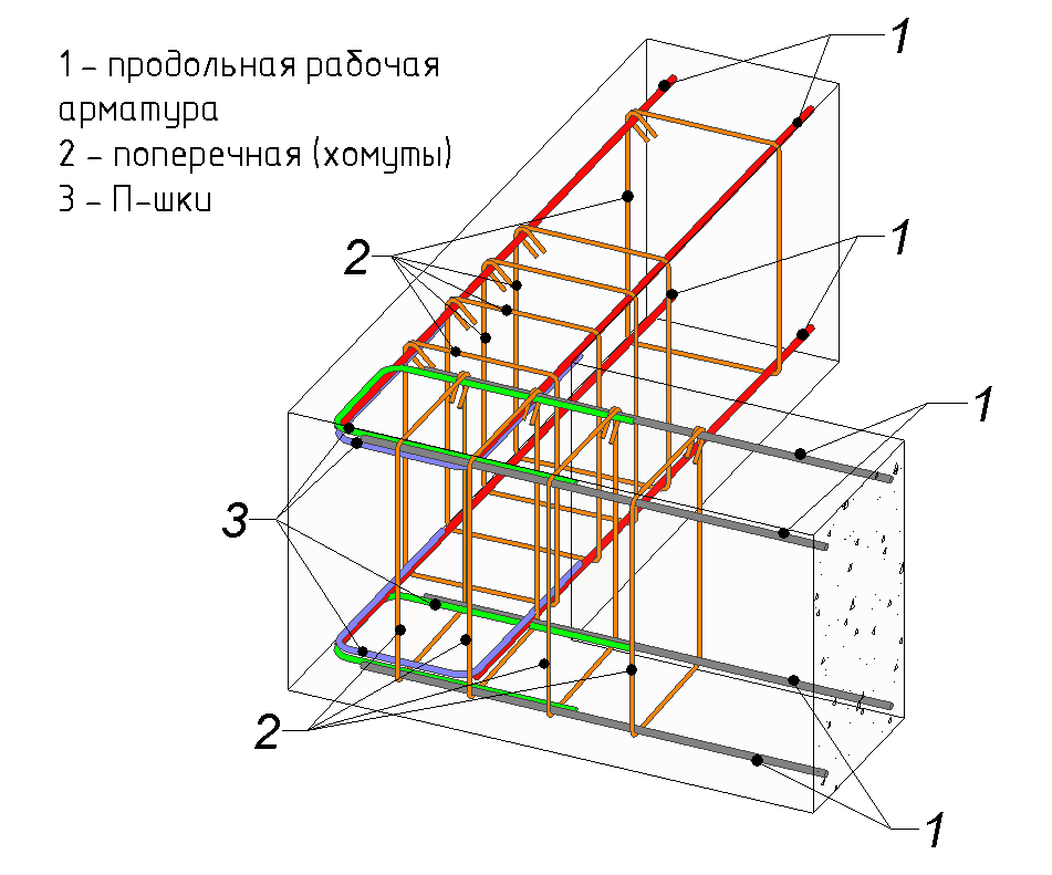
Reinforcement technology is the process of creating a spatial reinforcement cage. It consists of the following elements:
- longitudinal reinforcement;
- transverse;
- vertical;
- reinforcing clamps;
- knitting wire.
Longitudinal reinforcement is laid along the long side of the foundation, and the length of the rod usually reaches 6 or 12 m. It is this that resists stretching. Longitudinal reinforcement is performed along the top and bottom edges of the reinforced concrete structure.
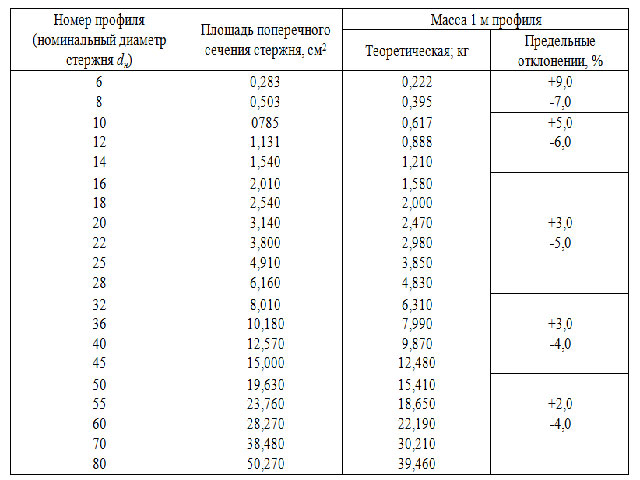
The laying pattern depends on the calculation of the required cross-sectional area of \u200b\u200bthe reinforcement. Such a calculation requires careful consideration of all loads on the foundation, including climatic loads from snow and wind, as well as the own weight of the foundation. The bearing capacity of the soil is taken into account according to geological research (geological section). In GOST 5781-82, table 1 contains the cross-sectional area for each rod diameter, it remains to decide how many rods to place on the upper and lower sides of the foundation.
However, for those who decided to build a house on their own, with their own hands, you can do without calculations, using the recommendations of clause 10 and section 5 of the Manual "For the design of concrete and reinforced concrete structures from heavy concrete without prestressing reinforcement." They indicate that the minimum cross-sectional area of \u200b\u200bthe reinforcement is Аs \u003d µ * b * ho, where:
Аs - cross-sectional area of \u200b\u200breinforcement;
µ \u003d 0.1% - percentage for bent structures;
b - section width of the strip foundation;
ho - the height of the working area of \u200b\u200bthe section (equal to half the height of the foundation section).
The diameter of the upper rods can be equal to the diameter of the lower ones, or they can be taken smaller. The maximum distance between the axes of longitudinal rods (pitch) is recommended to be taken no more than 1.5h or no more than 400 mm in beams and slabs, where h\u003e 150 mm is the height of the cross-section of the foundation (clause 10.3.8 of the SP and clause 5.13 of the Guide). Only in this case, effective work of concrete and reinforcement is ensured, limiting the width of crack opening between longitudinal bars.
The minimum pitch of the rods (distance between the axes) is limited for reasons of convenience in laying and compacting the concrete mixture and is equal to:
- d + 25 mm - for the lower reinforcement row;
- d + 30 mm - for the top.
Let's consider an example:
It is necessary to perform the reinforcement of the strip foundation 400 mm wide, 600 mm high. You need to calculate how many rods you need and choose the diameter. The minimum cross-sectional area of \u200b\u200bthe reinforcement is: Аs \u003d 40х30х0.1% \u003d 1.2 cm². The distance between the rods is 1.5x600 \u003d 900 mm, therefore, we will take no more than 400 mm. That is, 2 rods are installed along the width of the section. We select the diameter of the reinforcement according to GOST 5781-82 table 1: two rods of Ø 8 mm have an area of \u200b\u200bAs \u003d 2x0.503 \u003d 1.006 cm², which is less than the required 1.2 cm². Consider the following diameter Ø 10 mm. Аs \u003d 2х0.785 \u003d 1.57 cm². As a result, the layout of the rods is as follows: the upper and lower reinforcement should be taken equal to Ø 10 mm and laid in two rows.
Many builders today use the following rules to select the diameter of the rods: the diameter should be at least 10 mm if the side of the foundation is less than or equal to 3 m, and 12 mm for the side more than 3 m (see the Manual "Reinforcement of elements of monolithic reinforced concrete buildings" Appendix 1). However, the rules of the manual were developed for the design of monolithic reinforced concrete structures of multi-storey buildings, taking into account emergency loads and progressive collapse. Of course, for those who build a house with their own hands, the margin of safety will not hurt, but we are no longer talking about a reasonable consumption of reinforcement.
When installing reinforcement, one should not forget about the protective concrete layer - the distance between the side surface of the strip foundation and the reinforcement bar. A protective layer is necessary for several reasons: it protects steel from the corrosive effects of air and groundwater. In addition, for the normal operation of reinforced concrete, the reinforcement must be inside the concrete. The minimum layer size depends on the operating conditions of the structure and for structures located in soils, foundations with a concrete preparation device, it is equal to 40 mm and not less than the diameter of the working reinforcement (Table 10.1 SP and Table 5.1 of the Manual).
Read more about the calculation of reinforcement.
Transverse structural reinforcement
Structural transverse reinforcement means horizontal and vertical rodswhich:
- Maintain the longitudinal reinforcement in the designed working position.
- Prevents crack development.
- Accepts unaccounted for loads such as lateral buckling of the foundation.
The diameter of the transverse reinforcement in knitted bending frames is taken at least 6 mm. In Appendix 1 of the Manual "Reinforcement of elements of monolithic reinforced concrete buildings", transverse reinforcement is recommended to be performed in the form of a closed clamp with a rod diameter of at least 8 mm.
Device for bending armature clamps.
The distance between the rods (step) is taken to be no more than the doubled cross-section width and no less than 600 mm. With regard to the cover, the minimum distance between the bar and the concrete edge is 5 mm less than minimum size layer for longitudinal working reinforcement, that is, equal to 35 mm.
Materials used
Reinforcement materials are accepted in accordance with GOST 5781-82. The fittings are made of low-alloy and carbon steel in accordance with GOST 380-2015. The surface of the rods can be smooth or periodic. Depending on the properties, the material is divided into the following classes:
- A 240 (A-I);
- A 300 (A-II);
- A 400 (A-III);
- A 600 (A-IV);
- A 800 (A-V);
- A 1000 (A-VI).
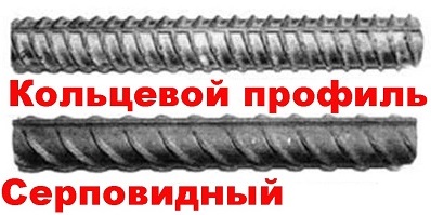
The foundation requires a crescent profile reinforcement.
The numerical code reflects the yield strength, for example, 240 corresponds to 235 N / mm². Among them, only A 240 (A-I) is made of a smooth profile. In the product range, products are limited to a diameter of 6 to 40 mm.
Frames can be welded or bonded. For binding and reinforcement, wire made of low-carbon steel GOST 6727-80, round (grade В-I) or ribbed (grade Вр-I), with a diameter of 3.0; 4.0.
Advice: The best solution for the foundation would be reinforcement grade A400 (AIII), the use of higher grades is not justified, because without preliminary stressing, its strength potential will not be used 100%.
It should be noted that in recent years, composite reinforcement made of fiberglass has appeared in the construction industry. The material is durable and lightweight. The material has many advantages: easy installation technology, has high anti-corrosion properties.
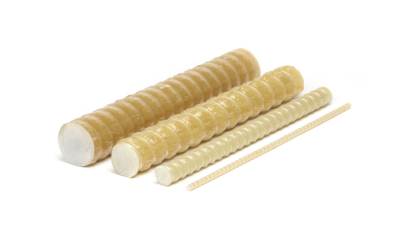
Photo of composite reinforcement.
However, the material also has disadvantages. It has self-extinguishing characteristics during combustion, but at a temperature of 200 ° C it loses its properties. In addition, it bends poorly, which makes it difficult to use bent elements. Many professional builders refused to work with this material due to the lack of practical experience (foreign experience was not taken into account) and recommendations for calculation.
But since July 2015, Appendix L has appeared in SP 63.13330.2012 with the rules for the design and calculation of structures. For those who prefer to do construction with their own hands, structural requirements for reinforcement are provided.
Reinforcement rules for corners and junctions
Often at the construction site, the reinforcement has to be made from residues, so the rods are overlapped, welded or special butt joints are used. When joining with an overlap, the ends of the reinforcement of a smooth profile are bent in the form of paws, hooks and loops, and the ends with a periodic profile can not be bent. The distance between the abutting bars can be from zero to 4 reinforcement diameters. The joint length is calculated according to the design manual, but cannot be less than 15 bar diameters or 200 mm.
Butt welded joints are made using brackets, and in mechanical joints, threaded and crimp couplings are used.
Important! The rules prohibit reinforcing corners with a simple overlap, since in this case the angle will not be integral and motionless.
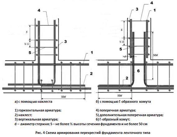
Corner and T-shaped junctions of the frames are made in three ways: with legs, additional curved clamps G and P of the form.
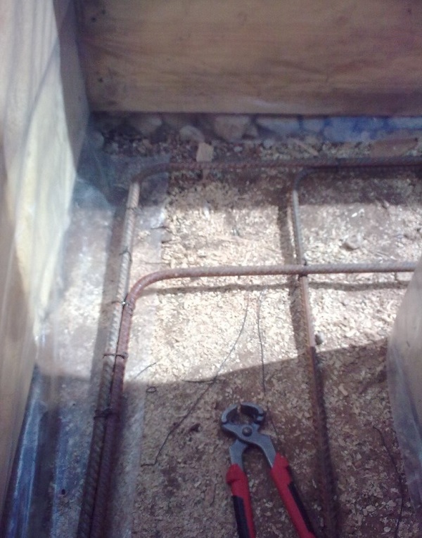
Photo of how to properly reinforce the corner.
Learn more about corner reinforcement.
Knitting reinforcement
It would seem that welded frames are faster and more convenient to use. However, builders prefer to knit space frames. And there are reasons for this:
- Welding reduces the quality of the metal.
- The settlement of the soil during the production of foundations provokes additional stresses at the joints. Welding joints do not always cope with loads and are destroyed. The connected parts do not change their position in space, but they have a certain mobility.
Advice! If you need contractors, there is a very convenient service for their selection. Just submit in the form below detailed description works that need to be completed and offers with prices from construction teams and firms will come to your mail. You can see reviews of each of them and photos with examples of work. It is FREE and non-binding.
The foundation is the foundation of any building. It is on a good foundation that the quality of house operation and its durability will depend. The foundation is usually hardened concrete. To stiffen the concrete base, it must be reinforced with special steel rods according to certain rules.
There is a strip foundation reinforcement scheme, following which the builder will lay a strong and durable foundation for the house.
What is a strip foundation and why should it be reinforced
The strip foundation is one of the most common concrete foundations. It is a strip structure made around the perimeter and the house, as well as in the places of partitions.
The strip foundation has the following advantages:
- withstands heavy loads of various buildings made of brick, stone, blocks;
- provides for the arrangement of the basement;
- suitable for non-uniform soils where there is a risk of subsidence and swelling.
Thus, the foundation experiences a double load: heavy walls press down on top, and soil tension acts from below. The latter fact is especially relevant for any building. Indeed, as a result of winter freezing, wet soil increases in volume. If the foundation is not rigid enough, then its integrity may be compromised, which will lead to the appearance of cracks in the walls and the risk of destruction of the house.
But concrete itself handles these loads well. So why do you need to additionally lay steel rods?
This is due to the fact that the load at different points of the foundation is different. After all, the condition of the soil is not the same in different places, like the pressure of the house, then the load on the foundation will be different.
To equalize this physical indicator, steel rods are laid in the concrete base, which ensure an even distribution of the load over the entire area of \u200b\u200bthe foundation.
Type and quantity of reinforcement for strengthening the foundation
Reinforcing rods are of 2 types: steel and composite. Metal fittings are used more often, as their effectiveness has been tested over the years.
The use of fiberglass is used for those buildings where the requirements for limiting radio interference, magnetic field, and chemical exposure are increased.
Metal fittings are rod and wire. For the strip foundation, bar reinforcement of a periodic profile of class A-3 or according to GOST A400 is taken. This building material has good adhesion to concrete and the lower and upper parts of the frame are knitted from it.
The vertical and transverse part of the frame is made of smooth rods with a cross section of up to 1 cm. Smooth rods are called assembly rods. Transverse reinforcement should be selected as class A-1 or in accordance with GOST A240.
Usually, the mesh frame is made in 2-3 rows. The step between the vertical rods: 40-70 cm, and the horizontal ones - 30-60 cm. If the buried foundation has a height of less than 1 m, then 2-3 longitudinal levels are needed for it.
For example, consider a foundation 60 cm high and 30 cm wide.This foundation is laid under a structure, the length and width of which are 5 m each.
In this case, a two-tier mesh is performed with a step of 0.5 m. For 4 longitudinal lines of 20 m each, 80 running meters of working reinforcement will be required. The calculation of the mounting vertical rods is taken taking into account the indents from the surface of 5 cm.If the number of intersections \u003d 51, then we get the total length of the rods: 1.4 m * 51 \u003d 71.4 m.It is recommended to buy material with a margin of 10%.
Thus, by adding the numbers, we get the total amount of required reinforcement: 80 + 71.4 + 10% ~ 170 running meters.
Video on how to properly reinforce the spatial frame of a shallow strip foundation:
Rules for laying steel rods in a concrete base
Before making the metal frame, the iron bars should be cleaned and checked for quality.
The technology of reinforcing the strip base is performed according to the following algorithm:
- A sand-crushed stone pillow, 5 cm thick, is poured into the dug trench. This is necessary to prevent corrosion of iron bars.
- Formwork is carried out and a thin concrete layer is poured.
- Transverse rods are laid on top with a step of 80 cm.
- Forming the frame, the longitudinal rods are laid, perpendicular to the previous rods, in 2 rows. The intersections are linked. The bottom level of the frame is ready.
- At the joints, vertical smooth rods are installed. It is important to observe perpendicularity when doing this.
- The upper tier of the frame is attached to the vertical rods. It is a frame in which the rods are fixed at intervals of 20 cm.
- The upper tier is completed with longitudinal rods, which are fastened to the rest of the rods with clamps or wire.
- The reinforcement skeleton is rigidly fixed to the formwork. The gap between the iron structure and the formwork should be 3-5 cm.
- They control the quality of fasteners and remove excess debris.
The most important thing when making a frame is to securely fasten the rods to each other, especially in the corners of the foundation. It is important to observe even angles and perpendicularity here. There are 2 ways to combine rods: welding and wire knitting.
Welding in private construction is undesirable, since this method does not provide the proper quality of the perpendicular structure. Builders often ignore the requirements of the norms and weld manually by resistance welding, not arc welding.
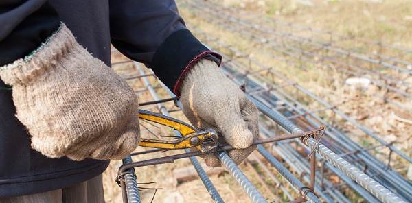
The preferred method for joining the rods is knitting with wire, 0.8-3 mm in diameter. This is done with a crochet hook. The quality of such a connection is much higher than in the previous version. The disadvantages of this method are: high labor intensity of the process and low rigidity in comparison with a welded structure.
Figure 1 shows a diagram of strengthening the foundation for a one-story house, 10x6 m in size.
As longitudinal rods, rods of class A-3 with a diameter of 12 mm are taken; transverse bars are reinforcement with a diameter of 8 mm, class A-1.
The step of the slabs is 0.6 m, and in the area of \u200b\u200bthe corners - 0.2 m. The corners and T-shaped intersections are reinforced with hats - reinforcement of class A-3, with a diameter of 12 mm. In the area of \u200b\u200babutments, the hats are overlapped, which is equal to: 50 * d, where d is the diameter of the bar.
Reinforcement of corners and T-joints can be done using special legs. They represent a kind of corners, with the length of the shelves equal to: 50 * d, where d is the diameter of the reinforcement. For example, if the diameter of the reinforcement is 10 mm, then the bend of the legs is 500 mm. An example of such an attachment is shown in Figure 2.
Summing up, we can highlight the basic rules for reinforcing the foundation:
- The diameter of the working rods must be at least 12 mm.
- Longitudinal (working) rods in combination with transverse reinforcement form a frame, the elements of which are welded or connected.
- For an average foundation size, 3-4 longitudinal bars are required.
- The diameter of the transverse rods is 6-8 cm, which are laid with a step of 200-600 mm.
- The thickness of the tape base is taken at least 300 mm.
- Corners and T-shaped intersections are reinforced with special clogs or paws. The diameter of these fasteners should be equal to the diameter of the working rods.
A metal frame in the construction of the foundation is a guarantee of a strong home and a comfortable stay in it.
How the French make a strip foundation:
Any building, regardless of its purpose, is unthinkable without a reliable foundation. The construction of the foundation is one of the most important and natural tasks of the entire construction cycle as a whole, and this stage, by the way, is often one of the most labor-intensive and costly - often up to a third of the estimate is spent on it. But at the same time, any simplifications, unreasonable savings on the quality and quantity of necessary materials, disregard for current rules and technological recommendations should be absolutely excluded.
Of all the variety of foundation structures, the most popular is the tape one, as the most versatile, suitable for most houses and utility structures erected in the field of private construction. Such a base is highly reliable, but, of course, with its high-quality performance. And the key condition for strength and durability is a competently planned and correctly carried out reinforcement of the strip foundation, the drawings and the basic principles of the device of which will become issues for consideration in this publication.
The article, in addition to diagrams, will contain several calculators that will help a novice builder in performing this rather difficult task of creating a strip foundation.
General concepts. Benefits of strip foundations
So, in short, several general concepts about the device of the strip foundation. By itself, it is a continuous concreted strip, without gaps in door or gateways, which becomes the basis for the construction of all external walls and internal capital partitions. The tape itself is buried at a certain calculated distance into the ground and at the same time protrudes from above with its basement part. The width of the tape and the depth of its laying, as a rule, is kept uniform throughout the entire length of the foundation. This shape contributes to the most even distribution of all loads falling on the base of the building.
Strip foundations can also be divided into several varieties. So, they are not only poured out of concrete, but also made prefabricated, using, for example, special foundation reinforced concrete blocks, or using rubble filling. However, since our article is devoted to reinforcement, in the future, only the monolithic version of the foundation tape will be considered.
The strip foundation can be classified as a universal type of foundation. Such a scheme is usually preferred in the following cases:
- When erecting houses from heavy materials - stone, brick, reinforced concrete, building blocks and the like. In short, when it is required to evenly distribute a very significant load on the ground.
- When the developer plans to get a full basement or even a basement at his disposal - only tape scheme can afford it.
- When constructing multi-level buildings, with the use of heavy floors.
- When the building site is characterized by heterogeneity of the upper soil layers. The only exceptions are completely unstable soils, when the creation of a strip foundation becomes impossible or unprofitable, and it makes sense to turn to another scheme. A strip foundation is also impossible in regions with permafrost.
The monolithic strip foundation has a considerable number of other advantages, which include durability, estimated by many tens of years, the relative simplicity and clarity of construction, ample opportunities in terms of laying engineering communications and organizing insulated floors on the first floor. In terms of its strength qualities, it is not inferior to monolithic slabs, and even surpasses them, while requiring less material costs.
However, one should not think that the strip foundation is absolutely not a vulnerable structure. All of the listed advantages will be valid only if the parameters of the erected base for the house correspond to the conditions of the construction area, the calculated load, and have a built-in reserve of strength. And this, in turn, means that special requirements are always imposed on the design of the foundation (any, by the way). And tape reinforcement in a series of these problems occupies one of the key positions.
The width of the foundation tape and the depth of its laying
These are two key parameters on which the reinforcement scheme of the future foundation tape will depend.
But the degree of penetration into the ground, strip foundations can be divided into two main categories:
- The shallow strip foundation is suitable for the construction of frame structures, small country houses and outbuildings, provided there is a sufficiently stable, dense soil on the site. The sole of the tape is located above the freezing point of the soil, that is, it usually does not fall below 500 mm without taking into account the basement part.
- For buildings erected from heavy materials, as well as in areas where the state of the soil is not stable, a deep belt is required. Its sole has already dropped below the level of soil freezing, at least by 300 ÷ 400 mm, and if there is also a basement (basement) in the construction plans, even lower.
It is clear that the height of the foundation strip as a whole, including the depth of its occurrence, are by no means arbitrary values, but parameters that are obtained as a result of carefully performed calculations. When designing, a whole array of initial data is taken into account: the type of soil on the site, the degree of their stability both in the surface layers, and the change in structure as it deepens; climatic features of the region; presence, location and other features of groundwater aquifers; seismic characteristics of the area. Plus, the specificity of the building planned for construction is imposed - the total load, both static, created only by the mass of the structure (of course, taking into account all its constituent elements), and dynamic, caused by operational loads and all kinds of external influences, including wind, snow and others.
Based on the foregoing, it is pertinent to make one important remark. The fundamental position of the author of these lines is that the calculation of the basic parameters of the foundation tape does not tolerate an amateurish approach.
Despite the fact that on the Internet you can find many online applications for carrying out such calculations, it would be more correct to entrust the issue of designing the foundation to specialists. At the same time, the correctness of the proposed calculation programs is not in any way disputed - many of them fully comply with the current SNiP and are capable of really giving accurate results. The problem lies in a slightly different plane.
The bottom line is that any, even the most perfect calculation program, requires accurate input data. But in this matter, it is impossible to do without special training. Agree that it is simply beyond the power of a layman to correctly assess the geological features of a site for construction, take into account all the loads that fall on the foundation tape, and with their expansion along the axes, to foresee all possible dynamic changes. But each initial parameter matters, and underestimating it may well then "play a cruel joke."
True, if it is planned to build a small country house or an outbuilding, then the invitation of a design specialist may seem like an excessive measure. Well, at his own peril and risk, the owner can build a shallow strip foundation, using, for example, the approximate parameters shown in the table below. For light buildings, a deeply buried tape is not required (a large deepening can even play a negative role, due to the application of tangential forces during frosty swelling of the soil). As a rule, in such cases, the maximum sole depth is limited to 500 mm.
| Type of building being built | Barn, sauna, outbuildings, small garage | One-story country house, including one with an attic | One- or two-story cottage for permanent residence | Two or three story mansion |
|---|---|---|---|---|
| Average value of soil load, kN / m ² | 20 | 30 | 50 | 70 |
| TYPES OF SOIL | RECOMMENDED DEPTH | TAPE POSITIONS | (Excluding the basement | FOUNDATION PARTS) |
| Strongly rocky ground, flask | 200 | 300 | 500 | 650 |
| Dense clay, loam that does not disintegrate after squeezing with the force of the palm | 300 | 350 | 600 | 850 |
| Caked dry sand, sandy loam | 400 | 600 | Professional calculation of the foundation is required | |
| Soft sand, silty soil or sandy loam | 450 | 650 | Professional calculation of the foundation is required | Professional calculation of the foundation is required |
| Very soft sand, silty soil or sandy loam | 650 | 850 | Professional calculation of the foundation is required | Professional calculation of the foundation is required |
| Peat bog | A different type of foundation is required | A different type of foundation is required | A different type of foundation is required |
We emphasize once again - these are only averaged values, which cannot be considered as the ultimate truth. In any case, if an amateur builder uses such sources, he takes a certain risk on his own responsibility.
Now - about the width of the foundation tape.
It also has its own peculiarities. Firstly, to ensure the rigidity of the foundation structure, it is customary to adhere to the rule that the total height of the tape should be at least twice its width - but this rule is not difficult to follow. And the second - the width of the tape in the region of the sole should be such that the distributed load is less than the calculated parameters of soil resistance, of course, also with a certain design margin. In short, a full-load foundation tape should be stable without sinking into the ground. In order to save materials, the base of the strip foundation is often made with widening to increase the support area.
Probably, it makes no sense to give here formulas and tabular values \u200b\u200bof soil resistance for independent calculations. The reason is the same: not so much the difficulty in performing the calculations, but rather the problems with the correct determination of the initial parameters. That is, again, it is better to turn to professionals on such issues.
Well, if a light structure or a country house is being built, then you can be guided by the fact that the width of the tape should be at least 100 mm more than the thickness of the walls being erected. As a rule, when planning a foundation on your own, they take round values \u200b\u200bthat are multiples of 100 mm, usually starting from 300 mm and above.
Reinforcement of the foundation tape
If a specialist is engaged in the design of the strip foundation, then the finished drawing will, of course, include not only the linear parameters of the concrete belt itself, but also the characteristics of the reinforcement - the diameter of the reinforcing rods, their number and spatial arrangement. But in the case when a decision is made to independently erect the foundation for a building, when planning the structure, it is necessary to take into account certain rules established by the current SNiP.
Which fittings are suitable for these purposes?
For proper planning, you need to understand at least a little about the range of fittings.
There are several criteria for the classification of reinforcement. These include:
- Production technology. So, the reinforcement is wire (cold-rolled) and rod (hot-rolled).
- According to the type of surface, reinforcing rods differ into smooth and with a periodic profile (corrugation). The profile surface of the reinforcement ensures maximum contact with the poured concrete.
- The reinforcement can be designed for conventional or prestressed reinforced concrete structures.
To create the reinforcing structure of the strip foundation, as a rule, they use fittings manufactured in accordance with GOST 5781. This standard includes hot-rolled products intended for reinforcing conventional and pre-stressed structures.
In turn, these fittings are classified into grades, from A-I to A-VI. The difference mainly lies in the types of steel used for the production and, therefore, in the physical and mechanical properties of the products. If low-carbon steel is used in the reinforcement of the initial classes, then in the products of high classes the parameters of the metal are close to alloyed steels.
It is not necessary to know all the characteristics of the reinforcement classes for self-construction. And the most important indicators that will affect the creation of the reinforcing cage are shown in the table. The first column shows the reinforcement classes for the two designation standards. So, in brackets the designation of the classes is given, the digital designation of which shows the yield strength of the steel used for the production of reinforcement - when purchasing material, such indicators may appear in the price list.
| Reinforcement class according to GOST 5781 | steel grade | Rod diameters, mm | Cold bending angle and minimum bending radius (d - rod diameter, D - mandrel diameter for bending) |
|---|---|---|---|
| A-I (A240) | St3kp, St3sp, St3ps | 6 ÷ 40 | 180º; D \u003d d |
| A-II (A300) | St5sp, St5ps | 10 ÷ 40 | 180º; D \u003d 3d |
| -"- | 18G2S | 40 ÷ 80 | 180º; D \u003d 3d |
| AC-II (AC300) | 10GT | 10 ÷ 32 | 180º; D \u003d d |
| A-III (A400) | 35GS, 25G2S | 6 ÷ 40 | 90º; D \u003d 3d |
| -"- | 32G2Rps | 6 ÷ 22 | 90º; D \u003d 3d |
| A-IV (A600) | 80C | 10 ÷ 18 | 45º; D \u003d 5d |
| -"- | 20ХГ2Ц, 20ХГ2Т | 10 ÷ 32 | 45º; D \u003d 5d |
| A-V (A800) | 23Х2Г2Т, 23Х2Г2Ц | 10 ÷ 32 | 45º; D \u003d 5d |
| A-VI (A1000) | 22Х2Г2АЮ, 20Х2Г2СР, 22Х2Г2Р | 10 ÷ 22 | 45º; D \u003d 5d |
Pay attention to the last column, which indicates the permissible bending angles and diameters of curvature. This is important from the point of view that when creating a reinforcing structure, come to produce bent elements - clamps, inserts, legs, etc. In the manufacture of conductors, mandrels or other bending devices, it is necessary to be guided by these values, since a decrease in the bend radius or an excess of the angle can lead to the reinforcement losing its strength properties.
Twigs class A-I are available in a sleek design. All other classes (with some exceptions, which, however, more depend on the individual requirements of the customer) - with a periodic profile.
For strip foundations in private construction, the best choice would be reinforcement of class A-III, in extreme cases - A-II, with a diameter of 10 mm and above.
For structural elements of an armored belt (clamps, jumpers), it is convenient to use a smooth rod of class A-I, with a diameter of 6 or 8 mm. The use of reinforcement of higher classes is unprofitable, due to its high cost, with an obvious lack of demand for such high physical and technical indicators.
"Classic" scheme of reinforcement of the foundation tape. Number of longitudinal rods
To begin with, consider a typical reinforcement scheme for straight sections of the foundation tape.
It is based on a rectangle with obligatory reinforcement levels above and below, made of longitudinal reinforcement (item 1), which are interconnected by horizontal transverse (item 2) and vertical reinforcement, thereby creating a kind of "box-shaped" structure. This arrangement of the belts makes it possible to maximally compensate for the two main multidirectional forces: from the total load created by the building and from frosty swelling of the soil. At the same time, the central part of the belt is least loaded, and if the foundation has a total height of up to 800 mm, then two belts are often enough.
With higher ribbons, the arrangement of the longitudinal belts in three or more tiers is used. But, as already mentioned, calculating such foundations on your own is a rather risky business.
The illustration shows the linking of longitudinal rods into a volumetric structure using reinforcement segments. This approach is quite acceptable, however, it is not convenient. The work will go much faster and better if you prepare clamps according to the size of the armored belt in advance on the conductor, and then tie all the details into a common structure.
Pay attention to the illustration, in which the arrows show two dimensions: H - the height of the reinforcement belt and K - its width. It should be correctly understood that this is not at all the height and width of the tape. Metal parts of the foundation must be protected from oxygen corrosion by a layer of concrete. According to SNiP, the minimum layer is 10 mm, but for a strip foundation, 50 mm to the edge of the concrete structure will be optimal. This must be taken into account when planning, and even during installation, simple devices will help to observe the necessary gaps between the reinforcement and the formwork. So, you can set the desired distance from the bottom of the formwork by placing fragments of bricks or installing special plastic racks under the lower rods.
And the required clearance from the side walls of the formwork can be observed if you use special clamps-"stars" that are simply put on the reinforcing bars.
Now - closer to the question of how many longitudinal reinforcement rods are still required, and what diameter they should be.
| Rebar application area | Minimum reinforcement diameter |
|---|---|
| Longitudinal working fittings on straight sections with a length of not more than 3 meters | 10 mm |
| The same, but with a section length exceeding 3 meters | 12 mm |
| Transverse reinforcement and clamps for compressed structural members. | Not less than 0.25 of the diameter of the working reinforcement, and at the same time - not less than 6 mm |
| Transverse reinforcement and clamps in the area of \u200b\u200bbending knitted frames | 6 mm |
| Clamps for ribbon knitted frame with a height not exceeding 800 mm | 6 mm |
| The same, but with a knitted frame height of more than 800 mm | 8 mm |
Well, the number of longitudinal rods required to ensure the design strength of the foundation tape directly depends on its size and on the diameter of the reinforcement used. In accordance with the current requirements of SNiP, the total cross-sectional area of \u200b\u200blongitudinal reinforcement rods must be at least 0.1% of the cross-sectional area of \u200b\u200bthe tape. Based on this, it is not difficult to make the necessary calculation. To make it even easier for the reader, there is a corresponding calculator below.
If you get an even value exceeding 4 rods, then it is recommended to distribute the reinforcement into three belts, placing the middle one in the center between the upper and lower ones. If an odd number is received, five or more pieces, then it makes sense to strengthen the lower tier of reinforcement with an unpaired rod - it is there that the highest bending loads are applied to the foundation strip.
Another rule: the requirements of SNiP established that the distance between adjacent elements of longitudinal reinforcement should not exceed 400 mm.
Tying rods of longitudinal reinforcement into a volumetric structure is carried out using harvested clamps. For their manufacture, a special device is usually built - it is easy to assemble it on a workbench or on a separate stand.
The step of installing the clamps also obeys certain rules. So, it should not be more than ¾ of the height of the foundation tape, and at the same time - not exceed 500 mm. In the areas of reinforcement - at the corners and abutments of the walls, clamps are installed even more often - this will be discussed below.
If in a straight section there is a need to connect two reinforcement rods located along the same line, then an overlap of at least 50d is made between them (d is the diameter of the reinforcing bar). When applied to the most commonly used diameters, 10 and 12 mm, this overlap is 500 to 600 mm. In addition, it is advisable to install an additional clamp in this area.
The connection of fittings and clamps into a single structure is made by tying them using galvanized steel wire.
Even if you have a welding machine at your personal disposal, and the owner himself considers himself to be a fairly experienced welder, all the same, the reinforcing structure must be made by wire twists. A poorly welded connection, and even worse, overheating of the reinforcement will lead to a sharp decrease in the strength characteristics of the structure being created. No wonder only highly qualified specialists are allowed to weld reinforcing structures in industrial construction. And besides, it is also necessary to use specialized fittings, in the designation of the class of which there is an index "C" - welding.
We will not dwell on the issues of practical knitting of the reinforcing cage in this publication - this topic deserves a separate consideration.
Reinforcement of complex sections of the frame structure
If everything is clear enough with the installation of the frame on the straight sections of the reinforcing belt of the strip foundation, then in difficult sections very often many make mistakes. This is evidenced by numerous photographs published on the Internet, which clearly show that two frames converging in a corner or adjacent to each other are simply connected by wire twists at the intersection points of the reinforcement.
Incorrectly mounted joints or abutments of reinforcing belts lead to the fact that the uniformity of distribution along the axes of the load falling on the foundation is disturbed, which in the future may well end with the appearance of cracks or even destruction of the tape in these areas. There are certain schemes for reinforcing such nodes - they will be discussed below in the table.
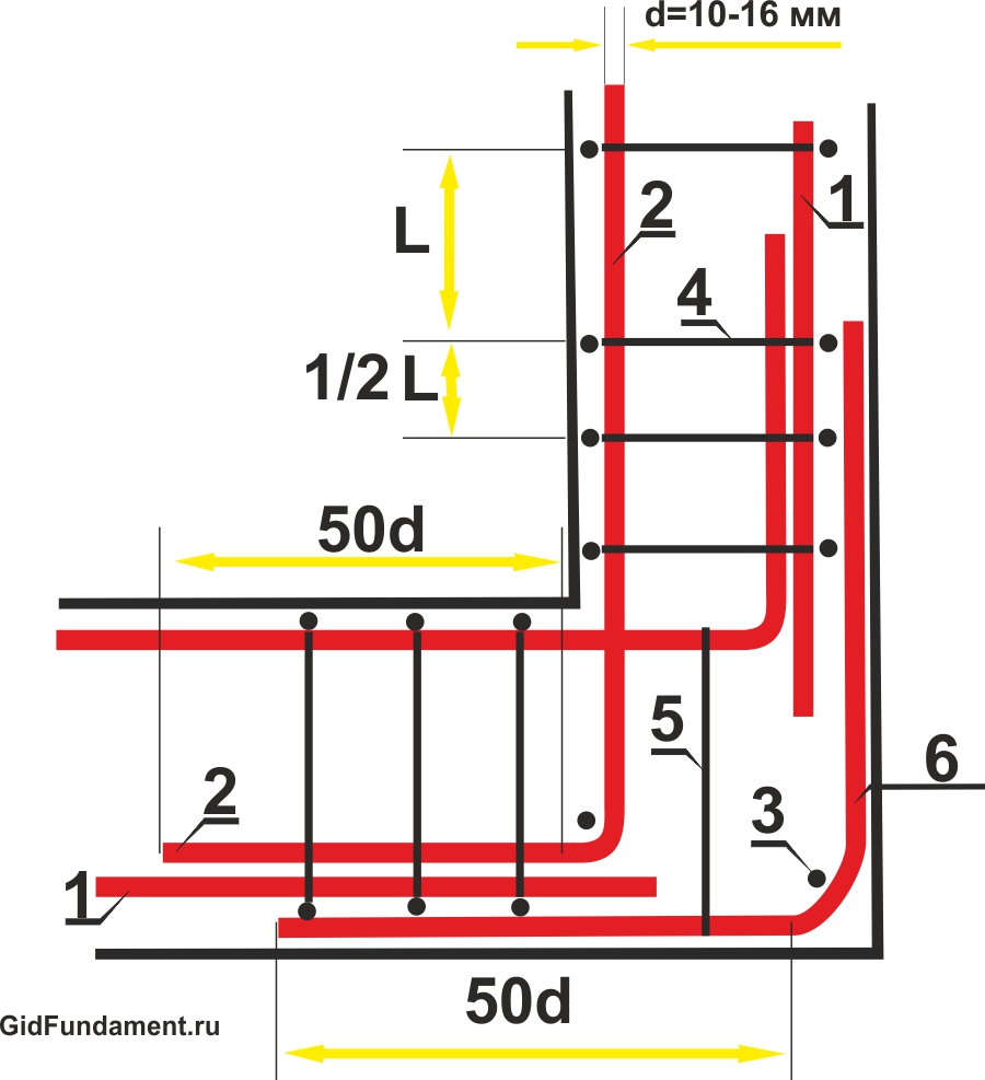
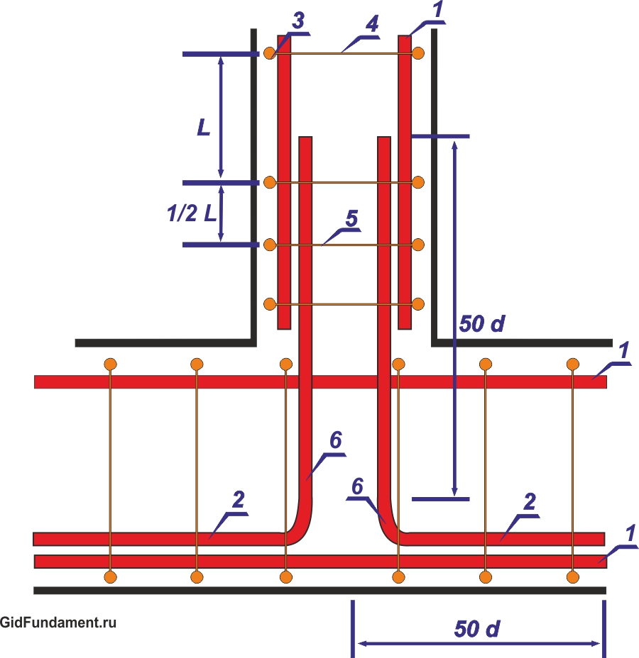
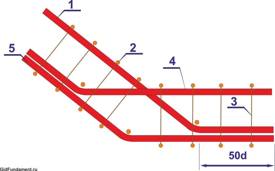
Basic schemes of reinforcement of corners and junction areas
(On the diagrams, the border of the foundation strip is shown in burgundy color, the longitudinal reinforcement rods are dark gray, the clamps of the frame structure are blue. In addition, individual specific elements of the reinforcement unit will be highlighted in different colors, which is stipulated in the text part. All illustrations are given in miniature, which can be enlarged mouse click).
| Reinforcement scheme for corners and abutments | Brief description of the circuit |
|---|---|
| REINFORCEMENT AT SITES OF OBSTANCY CHANGE IN THE DIRECTION OF THE FOUNDATION TAPE | |
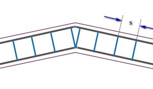 | If necessary, perform an obtuse-angle change in the direction of the foundation tape, provided that the angle exceeds 160 degrees, special reinforcement may not be provided. Longitudinal reinforcement bends at the desired angle. The pitch of the clamps (S) remains practically unchanged. The only feature is that two clamps are placed side by side at the bending point of the reinforcement located on the inner contour of the belt. |
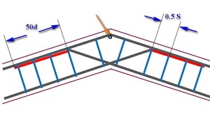 | A seemingly similar situation, but the angle of direction change, although obtuse, is less than 160 degrees. The amplification scheme is already different. The reinforcing bar running along the outer contour of the frame is simply bent in accordance with the desired direction. The bars converging but with the inner contour to the corner are made longer, so that they intersect with each other, reach the opposite side of the reinforcement belt, and end on it with paws bent at the desired angle (highlighted in red). The length of this curved leg part is at least 50d (d is the diameter of the longitudinal reinforcing bar). The paws are tied to the outer reinforcement rod, and the step of installing the clamps in this area is halved. At the top of the corner on the outer contour, a vertical piece of reinforcement is additionally installed (shown by an orange arrow). |
| REINFORCEMENT AT RIGHT ANGLES OF THE REINFORCEMENT FRAME | |
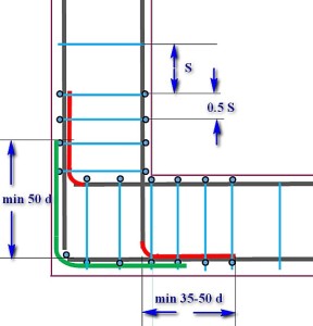
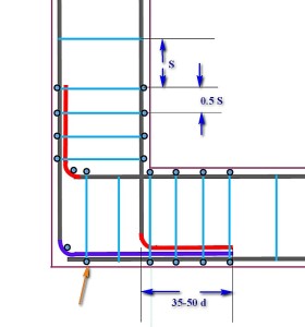 | Scheme with one large overlap and two "legs". The longitudinal reinforcement converging along the inner contour of the frame intersect with each other, reach the opposite walls of the formwork, where they bend with the formation of "legs" (shown in red) located in diverging directions. The minimum length of the "legs" is from 35 to 50d. One reinforcement on the outer contour is cut off at the corner, and the second, perpendicular to it, bends to form a large overlap (shown in purple), which should be of such length that at least completely overlap the “foot”. The entire structure is tied with clamps, the pitch of which should not exceed half the calculated one - 1 / 2S. The top of the bend angle is additionally reinforced with vertical reinforcement. |
 | The scheme is similar to the previous one. Longitudinal reinforcement is also wound up and bent with “legs”, and instead of an overlap, an L-shaped insert (shown in green) is installed along the outer contour of the reinforcement. The length of each side of this insert is at least 50d. Tying the knot - using clamps installed with a halved step. The rest is clear according to the scheme. |
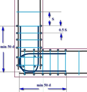 | A scheme that is convenient when the frames on each side are knitted separately, and then stacked into the formwork. In this case, the intersection and alignment of the frames into the overall structure is carried out using U-shaped inserts (shown in dark blue). The length of the "horns" of each of these overlays is at least 50d. Traditionally, in the reinforcement section, the step of installing the clamps is halved from the calculated one. Pay attention to the additional reinforcement of the area of \u200b\u200bintersection of the U-shaped inserts with vertical reinforcement. |
| REINFORCEMENT AT SEGMENTS OF THE SIDE JOINT OF THE FOUNDATION TAPE | |
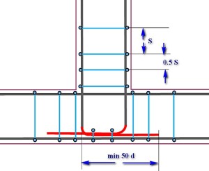 | The longitudinal reinforcement of the main foundation strip is not interrupted at the junction area. The longitudinal reinforcement bars of the adjoining tape intersect with the inner reinforcement contour, reach the outer side of the formwork and bend with “legs” (red), which are located in converging directions. Tying with clamps with a step reduced by half, and in addition to this, the section of intersection of the converging "legs" with the outer longitudinal reinforcement of the main tape is additionally tied. The length of the legs is at least 50d. |
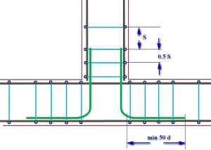 | A scheme that is convenient for the separate assembly of adjacent reinforcement cages. The frame of the main tape is not interrupted, and the frame of the adjacent tape ends along the intersection line. Tying into a single structure is carried out using L-inserts ( green color), which connect the longitudinal reinforcement of the adjoining tape with the outer contours of the main one. The side length of such an insert is at least 50d. All clamp connections are installed and tied with a halved pitch. |
 | Scheme for strengthening the abutment area using a U-shaped insert. As in other cases, the frame of the main foundation strip is not interrupted. The longitudinal reinforcement of the adjoining frame is brought to the outer contour and bent by “legs” (red), which are located in diverging directions. The side length of such a foot is from 30 to 50d. The main reinforcement is performed by a U-shaped insert (dark blue) with a length of each of the "horns" at least 50d. Tying - with the traditionally halved step for installing the clamps. Additional coordination with the installation of vertical reinforcement - in the area where the lower part of the U-shaped insert adjoins to the outer contour of the reinforcement of the main tape. |
One more nuance should be correctly understood. The schemes proposed in the table show the linking of the upper tier of the reinforcing belt. But exactly the same reinforcement should be provided in the lower chord, especially since the maximum loads usually fall on the lower part of the foundation strip.
Useful applications for calculating the amount of materials required
Below, the reader will be offered three calculators that will help in calculating the amount of material required to implement the selected strip foundation reinforcement scheme.
Calculator for calculating the number of main reinforcement
To calculate the required amount of the main longitudinal reinforcement of the strip foundation frame, you need to know several initial values:
- First of all, this is the total length of the foundation tape being created. Of course, this should include not only the outer perimeter, but also all internal jumpers, if they are provided for by the project.
- The second parameter is the number of longitudinal reinforcement bars. How to determine this amount - it was described above in this publication, with the attachment of the corresponding calculator.
- The third parameter is the number of gain sections, also discussed above. This includes all corners and junctions of the foundation strips. Naturally, in these areas, the consumption of reinforcement increases.
The accounting program, in addition, will take into account the need to overlap the reinforcing bars on straight sections of the tape. The overlap length is assumed to be 50d, that is, for the most commonly used reinforcement diameters, it will be from 500 to 600 mm.
The calculator will give the result in a piece quantity of a standard length reinforcing bar (11.7 meters). Sometimes the difficulties of transporting "long lengths" force buyers to purchase rods cut in two (5.85 meters). On the one hand, transportation is simplified, but on the other, the number of reinforcement overlaps during the installation of the frame inevitably increases, that is, the total required footage. The calculation program also provides for the second total value, expressed in the number of "halved" rods. This will make it possible to make a comparison and make a subsequent choice in favor of the first or second option.
The main task of the foundation is to transfer the load of the building (structure) to the ground. It is obvious that the concrete in the foundation will experience an internal compressive force - the walls press down from above, the soil repels from below. Concrete, unlike reinforcement, works very well in compression. So why is reinforcement used in the strip foundation?
Why do you need reinforcement in a strip foundation
During the operation of the building, sediment inevitably occurs. The soil under the foot of the foundation is compacted under pressure from above. The higher the pressure, the stronger the compaction occurs. In the event that it is strictly uniform along the entire length of the strip foundation, dangerous internal efforts do not arise in the foundation.
In practice, this situation is extremely rare. The asymmetry of shapes and loads leads to uneven pressure. In order to reduce the uneven settlement within the same building, foundation strips of different widths are usually used. More load means more width. But even in this case, it is impossible to completely equalize the pressure values \u200b\u200bunder the foundation sole.
In addition, it is impossible to vouch for the absolute ideality of the base of the foundation (soil). Various inclusions in the soil mass also form irregularities in the sediment. Uneven humidity also has a negative effect. Leakage of water-bearing communications, the absence of a blind area on the one hand, the likelihood of the appearance of various extensions (additional load gives additional draft) - all this forms an uneven sediment.
Relatively speaking, the soil surface under the foundation strip tends to become a "curve" in the vertical direction. The most dangerous areas are corners, as well as places with significant load differences (for example, with variable number of storeys, the presence of columns, additionally loaded pylons, etc.). This situation forms additional internal stresses in the foundation strip in the form lateral forces and bending moments. For their perception, reinforcement is introduced into the body of the foundations, since without it, cracks will appear not only in the tape, but also in the walls.
What reinforcement is needed for the foundation
By material, the fittings are divided into two types - steel and composite. The latter appeared relatively recently and, having a number of disadvantages (as well as advantages), today is rarely used in private construction.
Steel reinforcement is subdivided into rod and wire. To reinforce the strip foundation, bar reinforcement of a periodic profile is used as the main (working, they also say "longitudinal") and smooth in the form of an additional (transverse).
The working reinforcement must have good adhesion to the concrete to ensure joint work. Such reinforcement is made with a periodic profile, dividing it into strength classes. According to the GOST of the times of the USSR, reinforcement of class A-III or its analogue according to modern GOST A400 is used for private construction. As transverse reinforcement, smooth rods of class A-I or its modern analogue A240 are used. The fittings according to modern GOST are distinguished by a slightly modified profile (crescent). There are no fundamental differences between them.
Design requirements for strip foundations and their reinforcement
In view of some unpredictability of the degree of uneven settlement, an accurate calculation of the required diameter for a strip foundation is hardly possible. Therefore, over the decades of construction and operation of buildings, design requirements for the reinforcement of the strip foundation have been developed.
- The diameter of the working rods is taken at least 12mm.
- Working (longitudinal) bars are combined into lattice frames by means of transverse reinforcement by welding or knitting.
- The number of longitudinal rods in the frame is at least four (usually six).
- Step transverse reinforcement assigned within 200-600mm. The diameter of the rods is 6-8mm.
- The thickness of the strip foundation is usually taken equal to 300mm.
- Weak spots in corners and T-intersections are reinforced with reinforcement ties or tabs. Their diameter is taken to be equal to the diameter of the longitudinal bars.
Reinforcement scheme for the strip foundation. Longitudinal joining of working fittings. Reinforcement of corners.
We will consider the scheme of reinforcement of a strip foundation using the example of a one-story house with an attic measuring 10x6m in plan.
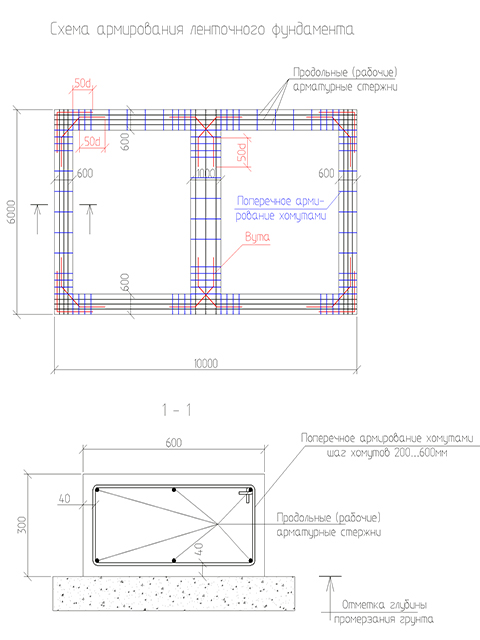
Longitudinal reinforcement is made with six rods of class A-III with a diameter of 12 mm. Transverse - with clamps from reinforcement class A-I diameter 8mm. The step of the clamps is adopted in the area of \u200b\u200bcorners and T-shaped intersections of 200mm, in other places 600mm.
The corners and places of T-shaped intersections are reinforced with corner and diagonal haunts made of class A-III reinforcing bars with a diameter of 12 mm. The overlap of the haunch in the area of \u200b\u200babutment to the longitudinal rods is assumed to be 50 diameters (50x12mm \u003d 600mm).
In this case, joining along the length of the working reinforcement rods can be performed with an overlap along the length of the identical length (600 mm). In such places, it is also advisable to install clamps with a rapid pitch (200mm). The length of the reinforcing bars reaches 11.7m. If possible, in order to reduce the amount of work, longitudinal connections should be avoided.
Reinforcement of corners and T-shaped intersections is also allowed to be performed with so-called legs. They represent the L-shaped bend of the longitudinal rods by the same amount of 50d.

When reinforcing strip foundations, the requirements for the protective layer of the reinforcement should be met - in order to avoid rusting. For foundations, the protective layer is 40mm at the side and top edges. For the sole, it is also allowed to take 40 mm in the case of a preparation device made of concrete class. В2,5 ... В10 100mm thick. Otherwise, the protective layer for the sole will have to be increased to 70mm.
How much reinforcement is needed for a strip foundation
An important issue before starting construction is its cost. It is impossible to determine it in the volume of the foundation without determining the required amount of reinforcement. But for an initial assessment, you can use the weighting factor of the reinforcement. Over the decades of design and construction, an indicator of the amount of reinforcement for low-rise buildings was derived. It is approximately 80 kg / m3. That is, if your strip foundation requires 20m3 of concrete, reinforcement on average will need 20x80 \u003d 1600kg. At the same time, it is not difficult to calculate the required volume of concrete - you just need to know the perimeter of the building, the length of the load-bearing internal walls, set the tape height of 300 mm and multiply by its width.
In conditions of economy, it is advisable to perform a more accurate calculation before purchasing fittings. To do this, you will have to draw a reinforcement scheme, determine the total molding of longitudinal and transverse reinforcement, vut, add 5-10% for trimming and then multiply the obtained data by the weight of a running meter for each of the diameters.
Strip foundation reinforcement - knit or cook?
Reinforcing bars are combined into frames by welding or knitting. Each method has its own advantages and disadvantages.
The main disadvantage of a welded joint is the impossibility (in accordance with the current norms and standards) to make a high-quality transverse connection with a hand electrode.
In the factory, frames and nets are welded by contact, not arc welding. In practice, builders often neglect the requirements of the norms, and cook by hand. As a result, very often there is either a lack of penetration (the connection is not strong enough) or an undercut (weakening of the longitudinal bar). In addition, fittings of class A-III are allowed to be made of steel grade 35GS, which has problems with weldability. If we add the need for welding machine, the ability to own it, significant energy consumption, the benefits of a knitted connection become obvious.
Knitted connection is done using knitting wire with a diameter of 0.8-3mm.
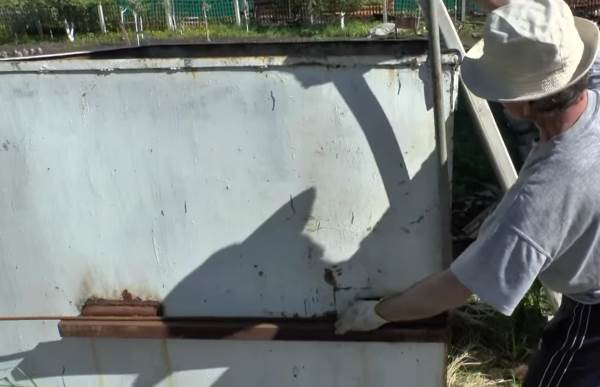
A crochet hook is used as a tool. (See the photo at the beginning of the work.) The advantages of such a connection are the absence of all the disadvantages characteristic of a welded joint, but there are also their own - high labor intensity, lower rigidity in comparison with the welded version (it is eliminated by means of additional diagonal rods-spacers to give the frame stage of concreting).
When welded joints transverse reinforcement is made with separate rods welded to longitudinal ones. In this case, their location should be both vertically and horizontally. With the knitted version, the clamps of a closed section are bent according to the pattern, which encircle the working rods. The template is a sturdy table with reinforcing stubs driven into it. Their location on the table corresponds to the position of the longitudinal bars in the section of the foundation strip. By bending the rods around the short ones with a piece of pipe as a lever, you can make the clamps yourself.