Left: diagram of the reinforcement of compressed elements: 1) longitudinal bars; 2) transverse;
Right: Reinforcement of compressed members with random eccentricities
The reinforcement of compressed elements consists of longitudinal and transverse rods (clamps), located, as a rule, at equal distances from each other. Longitudinal reinforcement is placed according to the calculation and takes part of the load acting on the element. Clamps are mainly designed to ensure the design position of the reinforcement and to prevent buckling of the longitudinal bars under the action of an external load. In addition, the clamps prevent the development of lateral deformations of the element, thereby somewhat increasing the resistance of concrete to compression.
Columns with a section of 400x400 mm can be reinforced with four rods. If the flat frames of the opposite sides of the column have intermediate longitudinal rods, then the latter are connected at least one and at least 400 mm later by means of pins. Hairpins are not installed if the column face width is 500 mm, if the number of rods on this face does not exceed 4.
Cross rods (clamps) should be located at distances of no more than 15d in knitted frames and 20d in welded frames (d is the smallest diameter of longitudinal compressed rods). The distance between the transverse rods (clamps) in all cases should not exceed 500 mm. The distance between the clamps within the joint of the overlapped compressed reinforcement without welding should be no more than 10d.
The diameter of the transverse rods (clamps) is set without calculation and in knitted frames is taken equal to at least 5 mm, as well as at least 0.2d with clamps made of ordinary wire class B-I with a diameter of 5 mm or from steel of class A-III and 0.25 d with clamps made of steel of other types (d is the smallest diameter of longitudinal compressed rods).
In welded cages, the minimum diameter of the transverse bars is taken from the welding condition.
For elements with a circular or polygonal cross-section, indirect reinforcement in the form of spirals or welded rings has become widespread. For elements with rectangular cross-section, volumetric indirect reinforcement in the form of frequently placed transverse welded meshes is used. Indirect reinforcement in the form of transverse meshes is widely used for local reinforcement of reinforced concrete precast columns near joints and also in the anchorage zone of prestressed reinforcement.
Spirals and rings, like a cage, restrain transverse deformations of concrete that occur during longitudinal compression, and thus cause an increased resistance of concrete to longitudinal compression, including after the appearance of the first longitudinal cracks in it.
Indirect reinforcement is expedient by calculation if the bearing capacity of the element, determined by the formulas, is higher than its bearing capacity, determined by the full section of the element and the value of the design resistance of concrete Rb, excluding the indirect reinforcement.
In the case of columns passing through several floors, at least the corner longitudinal bars should be passed through the floor as a connection reinforcement with the overlying column. The rods required for this purpose must be bent.
9. Calculation of cracking in centrally tensioned prestressed members.
When designing reinforced concrete structures, it is necessary to ensure not only their strength (the first group limit states), but also the required crack resistance and stiffness (the second group of limiting states).
Under crack resistance reinforced concrete structures understand their resistance to the formation and opening of cracks.
The calculation according to the 1st category of requirements for crack resistance is carried out for design loads with a safety factor for the load (as in the calculation of strength), the calculation of structures of the 2nd and 3rd categories of requirements for crack resistance lead to the effect of the design loads according to the 2nd group. .from. with a coefficient (numerically equal to the standard loads).
For the 1st category, prestressed structures are calculated that are under pressure of liquids or gases (tanks, pressure pipes), as well as those operated below the groundwater level with a fully extended section. Other prestressed elements, depending on the operating conditions of the structure and the type of reinforcement, must meet the requirements of the 2nd or 3rd category. All structures without prestressing must meet the requirements of the 3rd category.
1.1. Calculation for the formation of normal cracks
The calculation is based on stage Ia of the stress-strain state of a reinforced concrete element.
Calculation prerequisites:
The hypothesis of flat sections is considered valid;
The stresses in the concrete of the tensile zone are uniformly distributed and equal in magnitude; the stress diagram in concrete in the tensile zone can be replaced with a rectangular one;
The greatest elongation of the extreme stretched fiber take equal to the ultimate tensile strength of concrete
The stresses in non-stressed reinforcement of prestressed reinforced concrete structures are equal to the sum of the values \u200b\u200bof the compressive stress from shrinkage and creep of concrete and the increment in tensile stress due to deformations of tensile concrete
For tensile members, it is effective to use high-strength prestressed reinforcement. In order to limit the crack opening width, it is advisable to use smaller diameters with a larger number of rods.
Under central tension until cracks appear, most of the force N is absorbed by the concrete and less by the longitudinal reinforcement. Reinforcement stresses before cracking in concrete
s s \u003d e btu E s "15 × 10 -5 × 20 × 10 4 \u003d 30 MPa.
After the appearance of a crack, all forces in the section with a crack are absorbed by the reinforcement, as a result of which the stresses in it increase sharply.
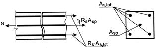
The strength of the centrally stretched element will be ensured if the condition
N £ hR s × A sp + R s × A s, tot
where h is a coefficient that takes into account the increase in the design resistance of prestressed reinforcement.
The nature of the destruction of eccentrically stretched elements depends on the magnitude of the eccentricity. In this case, two cases are possible.
Case 1 - an external longitudinal force is applied between the resultant forces in the reinforcement (small eccentricities).
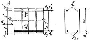
Strength conditions are obtained by compiling the equations of the equilibrium of moments (relative to the centers of gravity of the reinforcement):
N x e £ R s x A s 'x (h 0 - a');
N × e ’£ R s × A s × (h 0 - a’)
Case 2 - the external longitudinal force is outside the distance between the resultant forces in the reinforcement (large eccentricities).
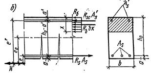
Strength conditions will take the form:
N × e £ R b × b × x × (h 0 - x / 2) + R sc × A s ’× (h 0 - a’);
N \u003d R s × A s - R b × b × x- R sc × A s ’
10. Slab design.
Floor slabs are supported by crossbars, working for bending and to reduce material consumption are designed with lightweight hollow and ribbed ones. When concrete is removed from the tensioned zone, only the ribs are retained, the width necessary to accommodate the welded frames and ensure the strength of the panels along the inclined section. In this case, the slab in the span between the girders works for bending between the ribs. If a smooth ceiling is required, a lower shelf is created, which forms a closed cavity. The upper flange of the slab also works for local bending between the ribs.
The general design principle for floor slabs of any cross-sectional shape is to remove as much concrete as possible from the stretched zone while maintaining the vertical ribs that ensure the strength of the element along the inclined section, in conjunction with the manufacturer's technological capabilities.
The calculated span of the plates l 0 is taken equal to the distance between the axes of its supports; when resting on the top of the crossbars l0 \u003d l - b / 2 (b is the width of the crossbar); when resting on the ledgers l0 \u003d l - a - b (a - shelf size). With one end resting on the crossbar, the other on the wall, the calculated span is equal to the distance from the support axis on the wall to the support axis in the crossbar.
The cross-sectional height h of the slab should be selected so that, along with the strength conditions, the stiffness requirements (ultimate deflections) are met. With spans of 5 ... 7 m, the height of the slab section is determined mainly by the rigidity requirements.
The section height of prestressed slabs can be pre-assigned differently: h \u003d l 0/20 - for ribbed, h \u003d l 0/30 - for hollow-core slabs.
When calculating the bending moment strength, the rib width is equal to the total width of all plate ribs; the calculated width of the compressed flange is taken equal to the full width of the panel. Thus, the calculation of the strength of the plates is reduced to the calculation of the T-section with a flange in the compressed zone. In most cases, the neutral axis runs within the compressed flange thickness. For cases where the neutral axis also crosses the rib, the calculation is carried out taking into account the compression in the rib.
The transverse reinforcement of the slab is calculated from the condition of the strength along the inclined section along the calculated rib width b, - equal to the total width of all edges of the section. In hollow-core slabs less than 300 mm in height, it is allowed not to install transverse reinforcement if it is not required by design.
According to the formation or opening of cracks, as well as deflections, the slab is calculated depending on the category of crack resistance requirements. When calculating the deflections, the section of panels with voids results in an equivalent I-section. For panels with round voids, the equivalent I-section is found from the condition that the area of \u200b\u200ba round hole with a diameter d is equal to the area of \u200b\u200ba square hole with a side of 0.9d
The slab shelf works for local bending as it is partially restrained on the supports with a span l0 equal to the clear distance between the ribs. In ribbed slabs with ribs downwards, the flange is pinched by pouring concrete of the seams, which prevents the rib from turning. Bending moment ql ^ 2/11.
Welded meshes and frames made of ordinary reinforcing wire and hot-rolled reinforcement of periodic profile are used. As prestressing longitudinal reinforcement, bar reinforcement of classes A-IV, A-V, At-IVc, At-V, high-strength wire and ropes are used. It is possible to reinforce without prestressing the reinforcement if the span of the panel is less than 6 m. The longitudinal working reinforcement is placed over the entire width of the lower flange of the section of hollow panels and in the ribs of ribbed panels.
The transverse rods are combined with longitudinal mounting or working non-tensioning reinforcement into flat welded frames, which are placed in the ribs of the plates.
Anchors from corners or plates are welded to the ends of the longitudinal non-tensioned reinforcement of ribbed plates to fix the rods on the support. Solid slabs of heavy and lightweight concrete are reinforced with longitudinal prestressing reinforcement and welded nets. Mounting loops are laid at the four corners of the plates. In places where the hinges are installed, solid panels are reinforced with additional upper nets.
Erection joints of all types of slabs are performed by welding steel embedded parts and filling the joints between the slabs with concrete.
1.Formwork device
Climbing formwork
Sliding formwork
Volumetric movable formwork
Rolling formwork
Formwork-facing
2.Reinforcement work
Installation of stress-free fittings
Column reinforcement
Reinforcement of beams, purlins and girders
Quality control of work and acceptance of mounted fittings
3. Installation of building structures
Mounting accessories
Structural erection methods
Installation of reinforced concrete structures of multi-storey frame buildings
1 Formwork device
Formwork is the form into which reinforcement and concrete are laid on the construction site.
The formwork must be strong, rigid, stable, maintain the specified design shape and dimensions. The design of the formwork should ensure its quick assembly and disassembly, and the accepted option is the most economical in comparison with others.
On the basis of repeated use, inventory formwork is distinguished, i.e. reusable and stationary - used for only one structure or structure. One of the ways to reduce the cost of formwork is to reuse it.
Wooden plank formwork has a 10-fold turnover rate, waterproof plywood - 25-fold, metal - 100 and 300-fold, but has a high initial cost.
According to the material, the formwork is distinguished: plank, made of waterproof plywood, metal, made of synthetic materials and combined.
According to the method of production of work, formwork is:
Collapsible and adjustable;
Volumetric adjustable;
Sliding;
Lifting-adjustable;
Rolling;
Formwork-facing.
Dismountable formwork, the most common in comparison with other formwork, is used in the construction of foundations, walls, columns, beams, floor slabs and coverings. The formwork is small-panel, large-panel and block formwork.
Small-panel formwork consists of several types of panels: flat, L-shaped or curved. The dimensions of the boards are multiples of the module 100 mm in height (width) and 300 mm in length.
The area of \u200b\u200bthe panels is up to 2.0 m2, consists of a set of fastening elements and supporting devices, the mass of such formwork elements does not exceed 50 kg. Formwork assembly and disassembly is done manually.
In order to mechanize the formwork and reduce their labor intensity, small-panel formwork can be pre-assembled into large-size formwork panels or blocks, which are installed and removed by crane.
In the small-panel formwork, molds can be assembled for almost any concrete and reinforced concrete structures. The versatility of the formwork is achieved by the ability to connect panels on any edges.
Figure: 1.1. Small-panel collapsible formwork:
a - flat shields; b - corner boards; в - fastening elements; d - supporting devices; d - knot for attaching shields to the fight e - panel connection node; 1 - shield frame; 2 - shield deck; 3 - slab formwork shield in working position; 4 - fight; 5 - telescopic rack; 6 - girder truss; 7, 8 - sliding girders; 9 - mounting corner; 10 - corner post; 11 - traction; 12 - tapered spacer; 13 - washer; 14 - nut; 15 - tubular spacer; 16 - pad; 17 - hook; 18 - wedge; 19 - spring bracket
To reduce the labor intensity of the work, the small-panel formwork is enlarged and installed in the design position using a crane.
For the construction of monolithic walls of frameless civil buildings, large-panel formwork "Grazhdanstroy", "Monolitstroy", etc. are used.
Formwork "Grazhdunstroy" consists of shields, fastening elements, supporting and auxiliary devices. Formwork panels have a width of 0.9; 1.2; 1.5 and 1.8 m, height - 2.56; 2.76 and 3.06 m. They are made with a frame made of bent sections and a deck made of sheet iron.
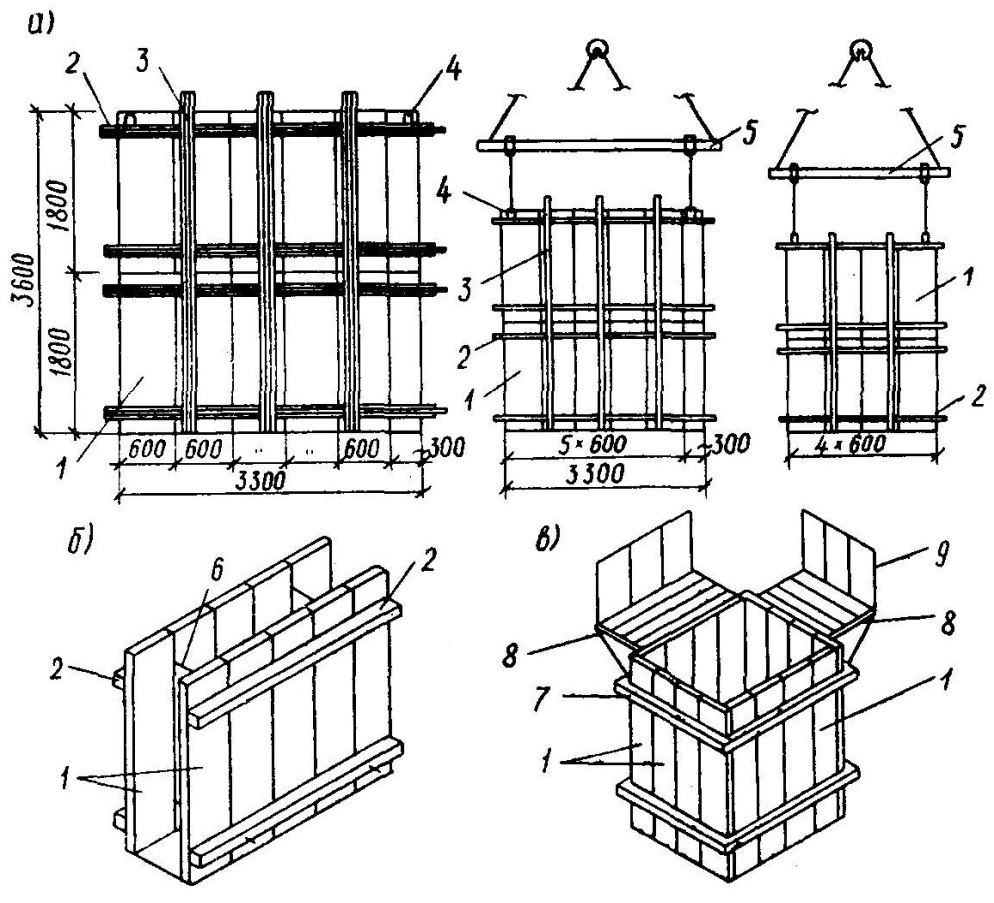
Figure: 1.2. Large-scale assembly schemes for small-panel formwork:
a - into large-panel formwork panels; b, c - in spatial blocks; 1 - shield; 2 - horizontal run-scrum; 3 - the same, vertical; 4 - mounting loop; 5 - mounting traverse; 6 - tie-bar; 7 - clamp; 8 - scaffolds; 9 - fence
In industrial construction, during the mass construction of columnar stepped foundations, various block forms are used, which perform a rigid structure. Surfaces (planes) in contact with concrete are tapering to facilitate mold removal. Jacks are also used to detach forms from concrete.
When reinforcing cages are installed and secured in block formwork, reinforcing-formwork blocks are obtained.
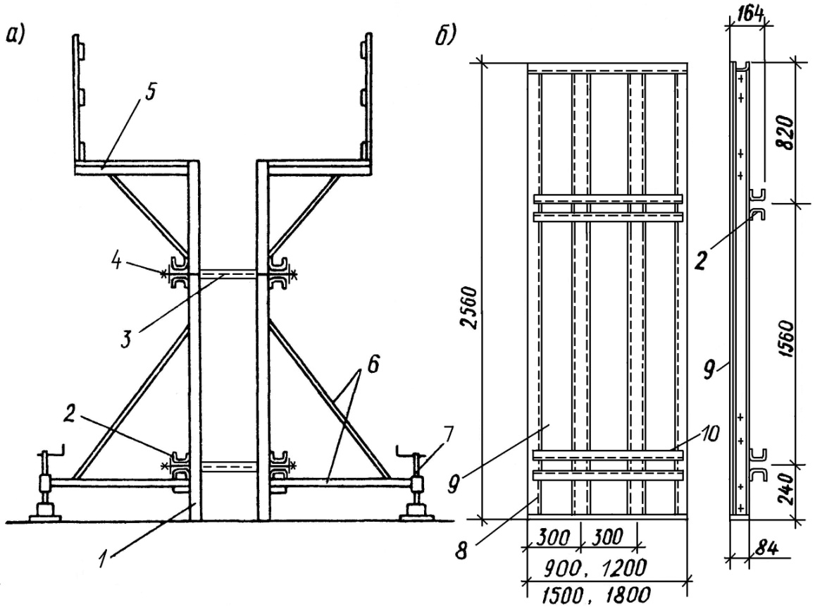
Figure: 1.3. Large-panel formwork scheme:
a - general view (fragment of wall formwork); b - formwork panel; 1 - shield; 2, 10 - shield run; 3 - tie-bar; 4 - nut; 5 - scaffolds; 6 - brace; 7 - jack; 8 - shield edge; 9 - shield deck
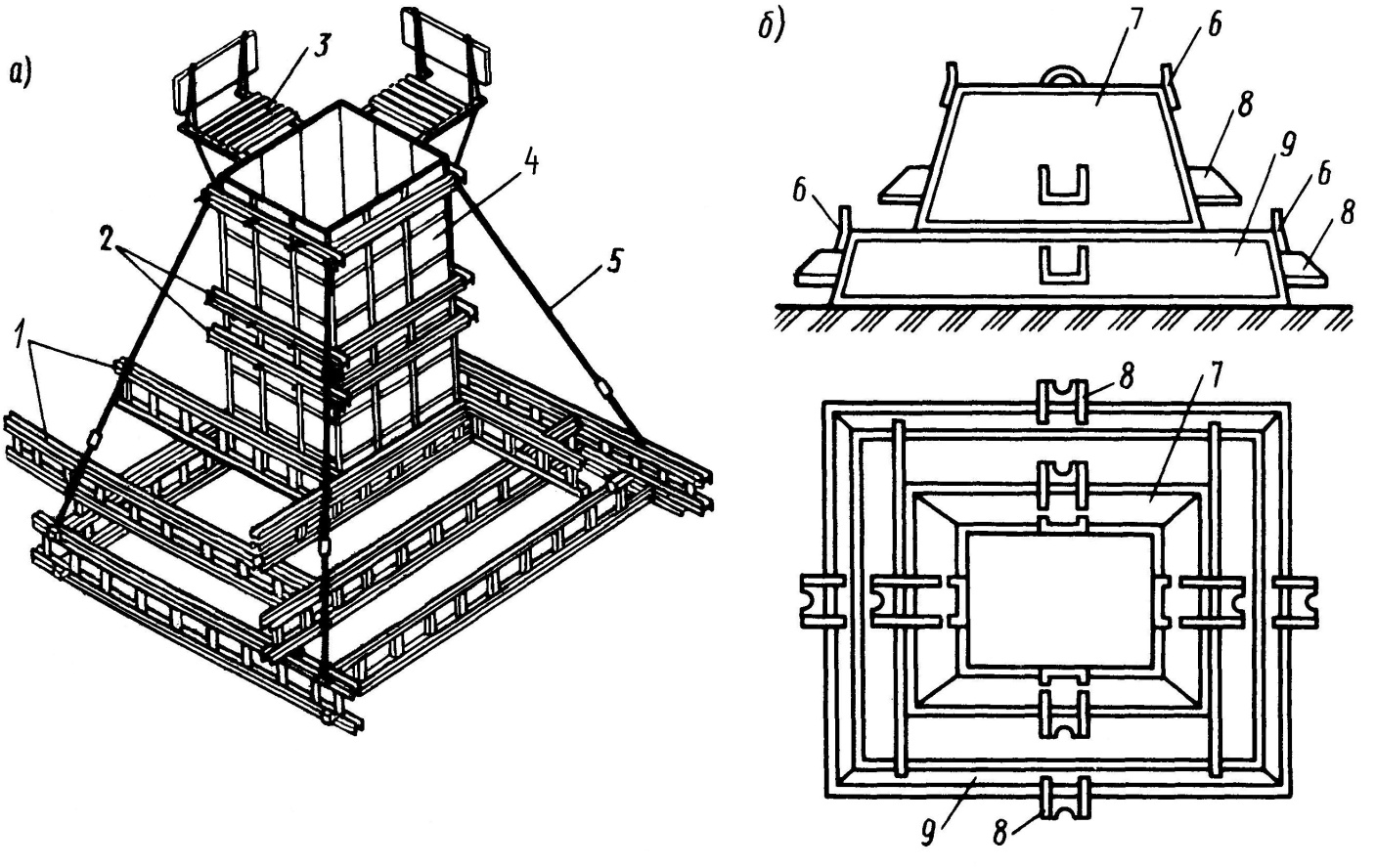
Figure 1.4. Block formwork:
a - universal (readjustable) formwork block; b - block form; 1 - bearing trusses; 2 - contractions; 3 - working platform; 4 - shields; 5 - brace; 6 - mounting loops; 7 - the shape of the columnar; 8 - bracket for supporting jacks; 9 - step shape
Formwork device for strip foundations
When installing strip foundations, inventory shields are connected to each other with bolts, spring brackets, pins. Shields are attached to inventory racks using tension hooks. The contractions of the opposing panels are fastened together with straps with screw or wedge locks. Contractions are used to perceive lateral pressure from the concrete mix. The required wall thickness is fixed with tie-rods or temporary struts.
Formwork device for columnar stepped foundations
The formwork of columnar stepped foundations is mounted in enlarged blocks. Collapsible-adjustable blocks are assembled from shields, corner elements and fights. The blocks are assembled in the following sequence:
Formwork panels are enlarged into panels. For this, the shields are laid out with the working planes downward according to the assembly scheme and connected to each other with bolts, spring brackets;
Then, scrapes are installed on the panels, to which the formwork panels are attached with tension hooks. If necessary, stiffening ties are installed and fastened with 24 mm W bolts;
Panels are combined into a spatial block using corner elements and contractions.
Block-molds of individual production for concreting free-standing foundations are made one-piece, made on a cone and sliding.
Before use, the work surface is cleaned and an anti-adhesive lubricant is applied using a spray gun. Installation and dismantling of blocks is carried out with a crane.
Climbing formwork
Climbing formwork is used for the construction of structures of variable cross-section in height (factory pipes, cooling towers, etc.). The formwork consists of internal and external shields, bearing rings, a support frame, mechanisms for radial movement of the external formwork, a working platform for external and internal scaffolding. The external formwork is assembled from two types of panels, which are rectangular and trapezoidal. Rectangular shields have dimensions of 2700 × 850 mm, trapezoidal - 818 mm wide at the top, 850 mm at the bottom, 2700 mm high. The deck of the panels is made of steel sheet 2 mm thick and framed with corners. Trapezoidal shields ensure the taper of the erected structure. The sheets are connected to each other with bolts passed through the holes in the corners of the framing and a metal plate installed at the upper edge of the sheets.
In the outer formwork, there are also end sheets that close the formwork. To tighten the outer formwork at the locations of the end sheets, tie bolts are installed.
The internal formwork is assembled in two tiers from steel panels 1250 mm high, 550 mm wide and 2 mm thick. On the outer surface of the sheets, strips with brackets are welded, which serve to install spacer rods in them, providing rigidity and geometric invariability of the inner formwork. A horizontal bar with rings is attached to the upper edge of the shield for tying the rope when rearranging the shields. To connect adjacent shields in one tier, a metal plate is attached to the horizontal bar. When installing the upper shield on the lower extreme brackets overlap the horizontal bar. The inner formwork is closed with the help of terminal boards having one bar with brackets.
Outside formwork panels, a working platform are suspended from the bearing rings, and suspended scaffolding is also attached. With the help of radial movement mechanisms, the outer formwork is raised, while changing the diameter of the structure to be concreted. The bearing rings are attached by means of hangers to the lifting head located on the mine hoist and designed to move the elements of the climbing formwork. The materials required for concreting are conveyed through a mine elevator. The average speed of concreting factory pipes is 1.2 - 1.5 m per day.
Sliding formwork
Sliding formwork is used in the construction of high-rise structures with a cross-section unchanged in height (silos, cylindrical pipes, stiffening cores, high-rise buildings). Sliding formwork consists of formwork panels, U-shaped jack frames, jack rods, working platform and hanging scaffolds.
Formwork panels are usually made of metal-wood with a height of 1.1 - 1.2 m. The labor intensity of formwork is reduced by enlarging the formwork panels. To reduce the frictional forces when lifting the formwork, the shields are tapering with a broadening in the lower part by 10 - 12 mm. The inner surfaces of the boards are treated with a release agent.
Jack U-shaped frames and jack rods are load-bearing elements of the formwork. Jack frames are installed through jacks on jack rods. Jack rods are made of steel St 5 with a diameter of 25 - 32 mm, the distance between the rods depends on the lifting capacity of the jacks, the rigidity of the form, the location and dimensions of the openings and is usually 1.5 - 2.0 m.
The flooring of the working platform is wooden, laid on metal purlins from bent profiles. The purlins are fixed to the uprights of the U-shaped frames. If necessary, suspended scaffolds are fixed to them. Concreting defects are eliminated from suspended scaffolds and the concrete surface is rubbed.
The formwork is lifted using jacks resting on jack rods, which are installed inside the formwork of the structure being erected. The jacks, rising along the jack rods, carry away the U-shaped frames with the formwork and auxiliary devices suspended from them.
Recently, it is planned to increase the lifting capacity of the jacks to 10 tons or more, the diameter of the jack rods to 50 mm. This will increase the step between the jack frames, which will make it possible to mount reinforcement with large-size frames and nets, as well as mechanize the supply of concrete.
For the construction of stiffening cores, elevators, silos in sliding formwork, the rodless method of concreting is used. With this method, the jack rods are replaced by screw rods located outside the concrete structure. The rigidity of the formwork is ensured by the upper and lower support rings. Application of this method allows to reduce the consumption of reinforcement, reduce labor intensity by eliminating welding and alignment of jack rods. From the bottom, extreme brackets overlap the horizontal bar, the metal plate is not attached. external formwork, works
Volume-shifting formwork
Volumetric movable formwork is used for the construction of high-rise, extended buildings with monolithic internal walls and ceilings. Formwork can be horizontally movable (tunnel) and vertically movable.
The horizontally movable formwork is used with the simultaneous construction of walls and floors. It consists of spatial U-shaped frames, from which the formwork block is assembled to the width of the building. The side surfaces of the frame serve as the formwork of the internal monolithic walls, and the upper one serves as the floor deck. The assembled formwork is set to the design position using a crane. After concreting and setting the stripping strength with concrete, the formwork is dismantled - the floor formwork is lowered with the help of jacks and the side surfaces are torn off the walls. Then the formwork is moved along inventory tracks laid along the floor to an adjacent position or special scaffolding. The scaffolds are arranged on the longitudinal side of the building. From the scaffold, the formwork is moved to the next floor.
A type of volumetric-movable formwork for horizontal movement is a formwork made of L-shaped panels. The panels are connected by adjustable struts and a central insert. To align the movement of the shields, screw jacks and hinge mechanisms are used. In this formwork, walls are concreted with a floor height of 2.8 and 3.0 m, and a wall pitch from 2.7 to 6.6 m.
When using vertically movable formwork, the floors are precast-monolithic or prefabricated. The formwork consists of a supporting frame with hinged shuttering boards fixed on it. The formwork is moved to the next position by a crane.
Rolling formwork
Rolling formwork is used in the construction of structures of linearly extended structures of constant and variable sections. Constructions of horizontally movable formwork make it possible to move the formwork panels along the axis of the structure to be concreted, to raise the panels vertically for tier concreting, to adjust the slope of the surface of the concreted structures.
The formwork for the construction of walls is a spatial frame consisting of racks, two trolleys, a connecting beam and metal formwork panels. The shields are placed between the guide posts, which fix the position of the shields, perceive the pressure of the concrete mixture and transfer the forces from the horizontal movement mechanism - the shields. Shields are moved vertically by an electric winch mounted on the upper beam. Outrigger consoles on boards with a deck and fencing serve as working scaffolds. To receive the concrete mixture, a receiving hopper with a vibrator is installed on the scaffolds.
Along the wall being erected, the formwork is moved along a rail track from an autonomous mechanical drive or an electric winch installed at the end of the section to be concreted.
Formwork-facing
Fixed formwork, depending on the purpose, is used:
Reinforced concrete - when erecting foundations of industrial buildings, technological equipment, when laying technological tunnels;
Expanded polystyrene blocks - as thermal insulation for the outer walls of residential buildings;
Asbestos-cement and metal formwork - they act as waterproofing.
The cladding formwork is attached to the main structure using anchoring loop-outlets, wire Ш 3 - 5 mm, embedded parts, and also gives the slabs a rough surface. Reinforced concrete formwork works in conjunction with monolithic concrete and is included in the design section of the structure.
2 Reinforcement work
Reinforcement works consist of a prefabricated reinforcement at the factory and its installation at the construction site.
Reinforcing steel with a diameter from 3 to 90 mm, hot-rolled and cold-drawn, wire, classes AI, A-II, A-III, A-IV are delivered to the construction site in the form of separate rods, 10 mm in diameter - in coils weighing 80-100 kg, coiled nets weighing up to 150 kg - made of wire Ш 3.0 - 3.5 mm.
Reinforcing steel, embedded parts and anchors arriving at the construction site are subjected to external inspection and measurements during acceptance. In the absence of the necessary data in the certificates of the manufacturers, they are subjected to control tests. The selection procedure, test methods and the number of control samples are taken in accordance with GOSTs, technical specifications, as well as additional project instructions.
Reinforcement types:
a - flat mesh; b, c - flat frames; d - space frame; d - frame of T-section; e - the same, I-section; g - curved frame; h - cylindrical frame; and - knitted frame with bent rods; 1 - end hooks; 2 - lower working rods; 3 - working rods with bends; 4 - clamps
According to the complexity of installation, the reinforcement is divided into heavy - with a diameter of more than 12 mm and light - with a diameter of less than 12 mm.
The fittings are flexible and rigid. Flexible reinforcement - smooth and periodic profile. Reinforcement bars are more economical. Rigid reinforcement is made of rolled profiles - channels, I-beams, angles. Formwork may be attached to rigid reinforcement.
Installation of stress-free fittings
Reinforcement of structures is performed with separate rods, flat and volumetric frames, meshes. Reinforcement cages and meshes are made in conductors that ensure the exact location of the elements to be welded. Load-bearing reinforcing cages using rods with a diameter of more than 32 mm must be manufactured taking into account the requirements for the manufacture, installation and acceptance of metal structures.
Places for slinging reinforcement products should be marked in accordance with the working drawings. When installing valves, the following requirements must be observed:
Before installing the reinforcement, the formwork must be checked;
The reinforcement should be mounted in a sequence that ensures its correct position and fastening, as well as ensure the required thickness of the concrete cover;
The required thickness of the protective concrete layer is provided by installing concrete, plastic and metal clamps;
The assembled reinforcement must be secured against displacement and protected from damage that may occur during the process of concreting the structure.
The displacement of reinforcing bars of cages and meshes should not exceed 1/5 of the largest diameter of the bar and 1/4 of the diameter of the bar to be installed. Butt joints of reinforcement are performed by resistance butt and spot welding, semi-automatic submerged arc welding and flux-cored wire in inventory forms, single-electrode or multi-electrode arc bath welding in inventory forms. It is allowed to weld butt joints with an arc bath, electrode or bath-seam welding with the remaining steel pads or pads, semi-automatic and single-electrode arc welding with multilayer seams, arc welding with extended seams with paired pads or overlapping.
Lap joints without welding are used when reinforcing structures with welded meshes or flat frames with one-sided arrangement of working reinforcement rods and with a reinforcement diameter not exceeding 32 mm. The amount of overlap (bypass) is established by SNiP, depending on the nature of the element's operation, the location of the joint, the class of concrete and reinforcing steel.
When joining welded meshes of round smooth rods, at least two transverse rods should be placed within the joint.
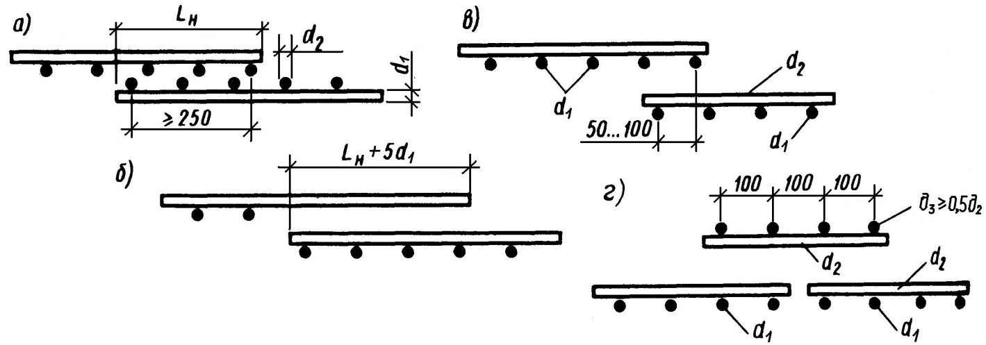
Figure: 2.1. Overlapping welded mesh:
a - from rods of a smooth profile with an overlap; b - the same, periodic profile; c - the same, in a non-working direction with a bypass; d - the same, with an additional mesh; d1 is the diameter of the working rods; d2 is the diameter of the distribution rods; d3 - diameter of additional mesh distribution rods
When joining meshes made of rods of a periodic profile, it is not necessary to weld transverse rods within the joint, but the length of the overlap in this case is increased by five diameters (see Fig. 2.1, b).
The joints of the rods in the non-working direction (transverse mounting rods) are performed with a bypass of 50 mm with a diameter of distribution rods up to 4 mm, and 100 mm with a diameter of more than 4 mm (see Fig. 2.1, c).
When the diameter of the working reinforcement is 26 mm or more, it is recommended to lay welded nets in the non-working direction close to each other, overlapping the joint with special butt nets with a bypass in each direction of at least 15 diameters of distribution reinforcement, but not less than 100 mm.
The assembled reinforcement is taken before the concrete mixture is laid and an act of inspection of hidden works is drawn up.
Stress reinforcement of structures
The tensioned reinforcing elements are harvested on technological lines. High-strength wire and reinforcing ropes are cut with mechanical shears or friction circular saws. Cutting them with an electric arc is not allowed. For bar reinforcement, hot-rolled steel of periodic profile of classes A-II, A-IIIв, A-IVн, At-IV, A-V, At-V, At-VI and high-strength wire B-II and Bp-II are used.
Prestressing in monolithic and precast-monolithic structures is performed on hardened concrete.
According to the method of laying prestressing reinforcement, there are linear and continuous methods. With the linear method, channels are left in prestressed structures during concreting. After the concrete has acquired a given strength, reinforcement is placed in the channels and its tension is made with the transfer of forces to the concrete of the structure. The linear method is used in the manufacture of beams, columns, frames, pipes, silos, etc.
The continuous method provides for winding with a given tension of an endless reinforcing wire along the contour of a concreted structure. The method is used for prestressing the walls of cylindrical tanks, gas tanks, sedimentation tanks, etc.
When tensioning reinforcement onto concrete of a structure, the following conditions must be observed:
The strength of the concrete of the structure and joints must not be lower than that established by the project, which must be confirmed by the results of testing control samples;
The actual dimensions of the structure must correspond to the design;
The concrete of the structure should be free of cavities, cracks and other defects that weaken the bearing capacity;
The structure to be crimped must rest in the places indicated in the project, and the supporting nodes must have freedom of movement;
In the places where anchors and jacks are installed, the concrete surface should be flat and perpendicular to the direction of the reinforcement; during installation, anchors and jacks must be centered along the axis of the reinforcement while maintaining this position during the tension period;
The stretched reinforcement must be injected, concreted or covered with anti-corrosion compounds provided for by the project, within the time frame excluding its corrosion.
In structures with a straight channel length of less than 18 m, the reinforcement is tensioned from one side. First, the reinforcement is tensioned with a force equal to 0.1 of the design force, at which the stress elements are straightened and tightly adhered to the concrete surface. An effort equal to 0.1 of the calculated one is taken as a zero reading during further control of the tension by the pressure gauge and deformations.
With the length of rectilinear channels more than 18 m and curved channels, the reinforcement is pulled from both sides of the structure.
The canals are injected with a solution of at least M 300 on cement of grades M 400, M 500 and washed sand. The canals are injected immediately after tensioning the reinforcement and are carried out continuously under a pressure of 0.1 MPa to 0.4 MPa. Stop pumping after the solution starts to flow out from the other side of the channel.
With channelless stress, the reinforcement is covered with an anti-corrosion compound, and then with fluoroplastic (Teflon), which has an almost zero coefficient of friction. When pulled, the rope slides relatively easily in the concrete body.
Reinforcement of the soles of columnar foundations
Reinforcement of the soles of columnar foundations is carried out with welded, steel, unified nets. The meshes are made in reinforcement shops.

Figure: 2.2. Reinforcement of the soles of foundations

Figure: 2.3. Concrete cover formation
The thickness of the concrete cover in the foundations must be at least 70 mm in the absence of concrete preparation and at least 35 mm in the presence of concrete preparation. For concrete preparation, concrete of class B 5 is used, for the foundation - B 12.5 (grade M 150, M 200
Column reinforcement
Reinforcement of columns is carried out with spatial and flat reinforcement frames, separate rods.
Reinforcement cages weighing more than 100 kg are fed and installed in the design position using a crane. Slinging of frames is carried out with semi-automatic slings.
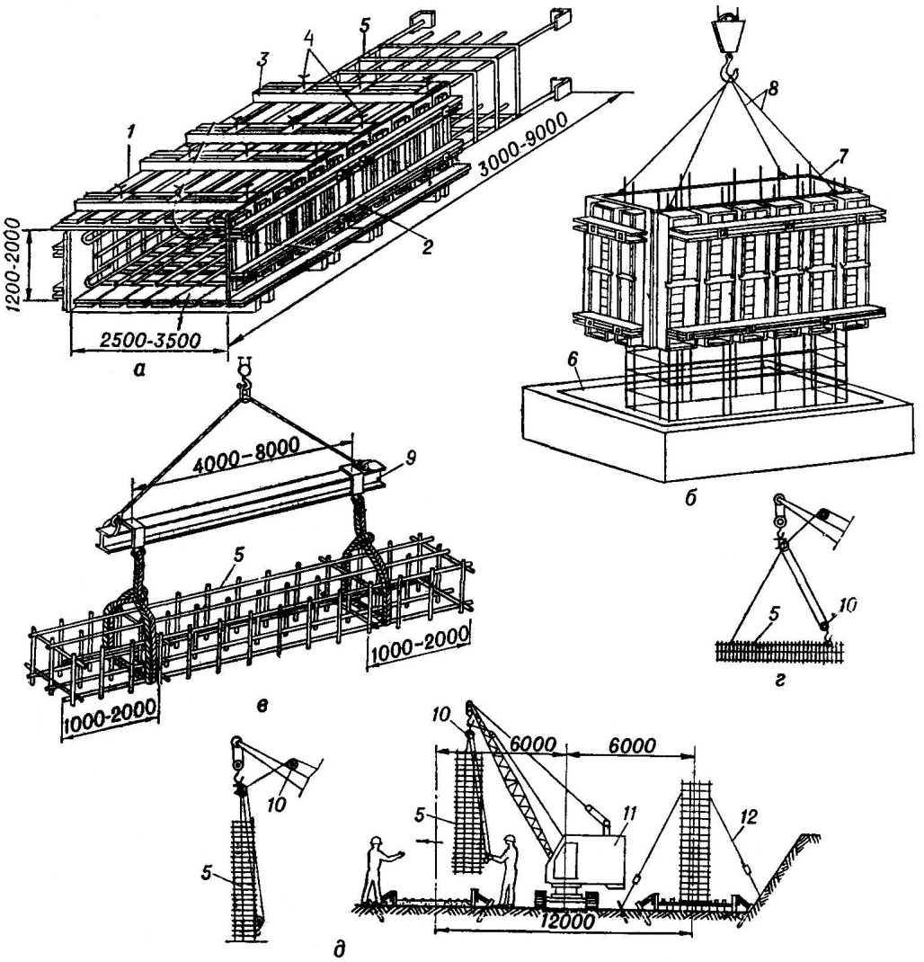
Figure: 2.4. Installation diagrams of reinforcement-formwork and reinforcement blocks:
a - general view of the reinforcement-formwork block of the sub-column; b - installation of this block; c - installation of the strip foundation reinforcement block; d, d - the same, columns; 1 - formwork panels; 2, 3 - contractions; 4 - fastening bolts; 5 - valve block; 6 - glass of the foundation; 7 - reinforcement-formwork block; 8 - slings; 9 - traverse; 10 - semi-automatic sling; 11 - crawler crane
Light column frames are manually installed in the formwork box, open on one side. The frame rods are seized by electric welding with the release of the reinforcement. After releasing the crane hook, the design fastening of the rods to the outlets or embedded parts is performed.
When reinforcing with flat frames, they are connected by welding at the installation site into spatial ones.
If the reinforcement of the columns is knitted in place from separate rods, then the outlets of the reinforcement of the underlying structures are straightened, the vertical rods are tied to them and fastened with clamps. The rods are fastened with knitting wire between themselves and with clamps.
Reinforcement of beams, purlins, crossbars
Reinforcement of beams, girders, crossbars is carried out with volumetric and flat frames. Heavy frames are lifted and erected with cranes, light ones manually. The ends of the frames are wound behind the column reinforcement outlets and attached to them. Flat welded frames are alternately lowered into the formwork and fixed in the desired position by welding the transverse rods.
Reinforcement of floor slabs, coatings
Reinforcement of floor slabs, coatings are performed after the installation of reinforcing cages of beams and girders. Reinforcement of the slabs consists in rolling out rolled nets along the formwork, which are fixed in the design position according to the markings made on the formwork. With double reinforcement of slabs, fixing the position of the upper meshes is made with reinforcing steel hinges.


Figure: 2.5. Scheme for fixing the position of the upper nets and ensuring the thickness of the protective layer
Reinforcement of floors, coverings with profiled sheet steel
Application of profiled metal decking:
Combines the functions of permanent formwork and working reinforcement;
Allows to exclude such labor-intensive processes as the device and dismantling of the formwork;
Reduce metal consumption for reinforcement;
Improve the aesthetic perception of structures.

Figure: 2.6. An example of a permanent formwork:
1 - monolithic concrete slab; 2 - profiled steel deck; 3 - bent plate anchors; 4 - spot welding
The use of flooring allows to reduce the labor intensity of work by 0.24 man-hours / m2.
To increase the connection of the flooring with concrete, anchors are welded, additional corrugations and dents are stamped.
Dents are arranged with a depth of 4 - 5 mm with a step of 150 mm.
The anchors are made of sheet metal 1.0 mm thick, with a height equal to 1/2 of the corrugation height. The anchors are fastened to the deck by spot welding.
Quality control of works and acceptance of mounted fittings
Reinforcement work is a hidden work. Each deviation from the project - replacement of the diameters of the reinforcement, its relative position - must be fixed by an act.
Before concreting, all mounted reinforcing structures are inspected, their dimensions are checked for design. At the same time, the location, diameter and number of rods, the distance between them, the correctness of the joints, the position of the pads to form a protective layer are checked.
Weld seams and assemblies made during installation are controlled by selective testing of samples. To test the strength of welded joints, 3 samples are taken from each batch. Welded joints made by resistance butt welding, when tested for strength, must withstand loads corresponding to the ultimate tensile strength of a given class of steel.
3 Installation of building structures
Installation of structures is an industrial, mechanized, complex process of erecting buildings and structures from prefabricated structures and elements manufactured in a factory.
Installation of building structures includes the implementation of transport, preparatory and assembly processes. Transport processes are associated with horizontal and vertical movement of structures and consist of loading, delivery, acceptance, unloading and storage of structures.
The preparatory processes include: making grippers, checking the correctness of the foundation, pre-assembly, reinforcement before lifting. The actual installation processes consist of slinging, lifting, installation, temporary fastening, alignment, permanent fastening and protection of embedded parts from corrosion.
Site preparation for installation work
Before starting the installation of structures, the following must be completed:
Backfilling of soil after installation of foundations, laying of underground structures;
Foundations for assembled structures of the entire building;
Roads for movement and operation of vehicles and crane tracks for assembly mechanisms;
Areas for temporary storage and pre-assembly of structures.
There should also be:
Sources of energy and water were supplied to the places of their consumption, lighting of the assembly site was arranged;
Mounting mechanisms, mounting devices, tools are prepared for operation;
Technical documentation developed and approved.
Incoming control. During the incoming inspection, they check the availability of documents on the structure (passports, quality certificates, etc.), the compliance of the geometric parameters of the structures with the design ones, the completeness of all embedded, fixing, fastening and slinging devices, the compliance of the strength properties of the material of structures with the requirements of standards and the project.
Mounting accessories
Mounting devices should ensure fast slinging and unstitching of structures, performance of operations related to the installation and alignment of mounted structures, stability of structures before their design fixation.
Limiting and adjusting devices of mounting devices must ensure the specified accuracy of alignment of structures.
The weight of manual mounting devices should not exceed: struts, guy wires and ties with a length of up to 3 m - 18 kg, with a length of up to 6 m - 35 kg; spacers - 5 kg; clamps - 7 kg; conductors - 50 kg. The mass of individual parts of mounting devices, assembled manually at the site of installation of structures, should not exceed 20 kg, and the length should not exceed 6 m.
When a steel rope bends around the elements of mounting devices, the ratio of the diameter of the bending element to the diameter of the rope must be at least four. In this case, splicing of the rope is not allowed.
Mounting devices are made in a climatic version according to the conditions of regions with moderate and cold climates.
Structural erection methods
Methods for assembling structures are fundamental, characteristic solutions that determine the technical policy in the production of installation work.
By the enlargement of the mounted structures, they distinguish element-by-element, block and installation with whole structures. With element-by-element installation, the structures are installed one on top of the other. They are widely used in the installation of reinforced concrete structures.
The block method of installation provides for the enlargement of structures into flat or spatial blocks of full or incomplete technological readiness. In blocks of full technological readiness, all types of
Similar abstracts:
Technological process of formwork for the construction of walls, columns and ceilings. Development of a construction schedule. Determination of labor and machine capacity of work. Calculation of the need for construction in temporary buildings and structures.
Description of the design of the main elements of the precast-monolithic system KUB-2.5 - floor panels, multi-storey columns, flights of stairs, ventilation blocks, external wall panels, truss system; their installation. Rules for monolithing joints.
Description of the necessary equipment and the project for the construction of an industrial five-story building. Selection and justification of production methods and technical means. Technology and organization of production of bored piles. Concrete stripping and maintenance.
Designing the production of earthworks. Determination of the composition of processes and initial data. Counting the volume of earthworks. Organization and technology of earthworks. Selection of the leading machine for the excavation. Calculation of operational performance.
Determination of the dimensions of the pit for the building. Calculation of the volume of soil of the cut off vegetation layer and soil developed in the excavation by an excavator, the volume of soil when cleaning the bottom of the excavation and making trenches for entry. Calculation of labor costs.
Conditions for the construction of a twelve-story residential frame building in Smolensk. Preparation of prefabricated reinforced concrete structures, monolithic pile and grillage foundations, hollow-core slabs, curtain wall panels.
The main direction of technical policy in the field of improving technologies for the production of construction and installation works. Monolithic concrete construction. Calculation of the scope of work. The choice of the assembly crane. Organization and technology of the construction process.
Installation diagrams for multi-storey columns using a set of individual assembly equipment. Installation of internal walls, stiffening diaphragms in a frame building. Installation of a girder-free stiffening panel. Laying tie and ordinary floor slabs.
The technique of reinforcing beams with prestressed flexible elements, the stages of its implementation and the equipment used. Carrying out installation work when hanging structures. Restoration and waterproofing device. Preparation of concrete mix.
Prefabricated slabs with a longitudinal arrangement of reinforced concrete monolithic beams and columns in a two-storey office building: layout, calculation and design; determination of standard and design loads, choice of material, its characteristics.
Column reinforcement. The range and assortment of reinforcing bars produced at metallurgical enterprises of the former USSR developed under the influence of demand driven by the massive development of precast concrete and in conditions practically isolated from the world market.
Until now, this circumstance, to a greater or lesser extent, for different metallurgical enterprises affects the loss of profit associated with the production of outdated types of reinforcing bars, with a high cost and low competitiveness.
The requirements for reinforcing bars by builders (consumers) at an early stage in the development of reinforced concrete remain relevant at the present time.
Taking into account the peculiarities of modern production and operation of reinforcing elements of precast and monolithic reinforced concrete (frames, nets, embedded parts, mounting loops, etc.), additional requirements for weldability, cold resistance, corrosion resistance have been added to the basic requirements for strength, deformability and adhesion to concrete. fittings, etc.
Due to the ever-increasing requirements for the quality of construction, the economic efficiency and reliability of the use of one or another type of reinforcing bars at the consumer become fundamental for its implementation at the manufacturer.
At the early stage of reinforcement production, the main determinants of its consumer properties were the technical capabilities of steel-making and rolling technological equipment. Then the builders were forced to be content with the reinforcement products produced by the metallurgical industry.
In connection with the rapid development of metallurgical production in recent years, almost all technological restrictions on the production of valves have been removed. At present, metallurgists are ready to manufacture those reinforcement products that can be effectively used in construction.
In accordance with SP 52-101-2003, it is recommended to use the following types of reinforcement for reinforcing reinforced concrete structures:
- hot-rolled smooth and periodic profile with constant and variable height of projections (respectively, annular and crescent profiles) with a diameter of 6-40 mm;
- thermomechanically hardened periodic profile with constant and variable height of protrusions (annular and crescent) with a diameter of 6-40 mm:
- cold-deformed periodic profile with a diameter of 3-12 mm.
The tensile strength class of reinforcement is indicated by:
- A - for hot-rolled and thermomechanically hardened fittings;
- B - for cold-deformed reinforcement.
Reinforcement tensile strength classes A and B correspond to the guaranteed value of the yield strength (rounded off) with a security of at least 0.95, determined according to the relevant state standards or technical specifications.
In necessary cases, requirements are imposed on reinforcement for additional quality indicators: weldability, plasticity, adhesion to concrete, cold resistance, corrosion resistance, fatigue strength, etc.
When designing reinforced concrete structures, reinforcement can be used:
- smooth class A240 (A-I);
- periodic profile of classes А300 (А-II), А400 (А-III, А400С), А500 (А500С, А500SP), В500 (Bp-I, B500C), where С - welded, П - increased adhesion.
Until the 80s of the last century, the main volume of production and use in construction was made up of reinforcement with a yield point σ t \u003d 400 MPa. During the period 1991 - 1997, the main European countries switched to a single class of welded reinforcement with a periodic profile for unstressed reinforced concrete structures with a yield strength σ t \u003d 500 MPa.
For columns and racks operating in central compression, as a rule, a square section, sometimes rectangular, circular or annular, is taken. If the eccentricity is large (usually with eccentric compression), the cross-section of the columns is assumed to be rectangular. In this case, the large sides of the rectangle are located parallel to the axis relative to which there is an eccentricity. Also, sections can be T-shaped or I-beams.
For the purpose of standardization, rectangular and square sections of columns are taken as multiples of 50 mm. For monolithic columns, a cross section of at least 250 mm is recommended.
Concrete for columns is used not lower than B15 (C12 / 15), and for very loaded ones not lower than B25 (C20 / 25).
Columns are reinforced with longitudinal bars of reinforcement with a diameter of ≥ 12 mm made of steel of class A400C or A500C and transverse bars or clamps made of steel of class A240C.
The dimensions of the cross-sections should be taken such that the flexibility l0 / r relative to any of the axes of the cross-section does not exceed 120. The thickness of the concrete cover should be taken ≥ the diameter of the longitudinal reinforcement bars and at least 20 mm. If strip, angle or shaped steel (in columns with a rigid frame) is used as longitudinal reinforcement, the thickness of the protective layer is taken to be ≥50 mm.
Light distance between vertical rods reinforcement placed vertically during concreting must be ≥ 50 mm. The distance between the bars of the longitudinal reinforcement, located horizontally or at an angle during concreting, is taken ≥ 25 m for the reinforcement of the lower part of the section and ≥ 30 mm for the reinforcement of the upper part of the section. In addition, this distance is taken in all cases ≥ the largest diameter of the reinforcement.
Cross bars or clamps are installed without calculation, but subject to the following requirements:
- with the column cross-section width ≤ 400 mm and the number of longitudinal bars ≤ 4, flat welded frames without additional bars or single clamps are designed;
- with a cross-sectional width\u003e 400 mm or a number of longitudinal rods\u003e 4, additional rods are installed on one side or double clamps are installed; - instead of double clamps, it is allowed to install connecting pins;
- bends of the clamps are provided at distances ≤ 400 mm across the width of the element cross-section.
The design of the knitted collars of the columns should be such that the longitudinal rods (at least through one) are located at the bend points of the collars, and these bends - at a distance of no more than 400 mm along the width of the column section. If the width of the edge is not more than 400 mm and the number of longitudinal bars on this edge is not more than four, it is allowed to cover all the longitudinal bars with one clamp.
The distance between transverse reinforcement bars is taken ≤ 15 d for knitted frames and ≤ 20 d for welded frames to prevent lateral buckling of longitudinal reinforcement bars. Moreover, in all cases, this distance is taken ≤ 500 mm, where d is the smallest of the diameters of the longitudinal compressed rods.
In columns with a longitudinal reinforcement coefficient of\u003e 3%, cross bars or stirrups are placed at distances ≤ 10d and ≤ 300 mm.
The diameter of the transverse reinforcement in welded cages is taken:
- 5-6 mm - with d \u003d 14-20 mm longitudinal rods;
- 8 mm - with d \u003d 22-25 mm;
- 10 mm - with d \u003d 28-32 mm;
- 12 mm - with d \u003d 36-40 mm.
In knitted frames, the diameter of the clamps is taken as ≥ 5 mm and ≥ 0.25d, in this case d is the largest diameter of the longitudinal reinforcement bars. As a rule, in the manufacture of knitted frames, clamps of A240C class wire with a diameter of 6-8 mm are used.
If the project provides for embedded metal parts, then they should not protrude beyond the plane of the edges of the elements. Embedded parts must be welded to the working reinforcement or be securely anchored into concrete by means of special anchor hooks or rods.
* * *
Design and calculation of slabs
General Provisions:
1. Class (grade) of concrete- not less than B30 (M400).
2. Protective layer
3. Longitudinal reinforcement- A III. The minimum diameter is d12mm. Step no more than 200 x 200 mm
4. Reinforcement percentage (for tensile reinforcement)µ \u003d 0.5 ... 2 (for high percentages of reinforcement, a beam (coffered) floor is required).
5. Transverse reinforcement- d8A I (set if necessary by calculation), structural transverse reinforcement - in the form of pins in the grid nodes in a checkerboard pattern;
design transverse reinforcement (in places of concentrated loads) in the form of specially designed reinforcement products.
Construction guidelines:
Minimum plate thickness h\u003e 200 (160) mm;
The ratio of the span of the slab to the thickness L / h is not more than 30;
Reinforce the slab with meshes in the form of the main (background) and additional reinforcement (in places of significant bending moments). It is recommended to set the top and bottom background reinforcement equal. It is recommended to place a 4ВрII - 100/100 mesh (in the thickness of the protective layer) under the lower design reinforcement, fasten the mesh knitting wire to the main reinforcement;
It is necessary to take into account the relative position of the bars of different directions of the same mesh - the bars of the working direction should be installed as close as possible to the edge of the slab ("Symmetrical" reinforcement scheme);
If it is difficult to choose the working direction of the slab, a "skew-symmetric" reinforcement scheme is used;
The mutual arrangement of the rods should be indicated on the working drawings.
Calculation instructions:
The safety factor (in addition to SNiP) shall be assigned: for plates working in one direction [k] \u003d 1.25, for plates working in two directions [k] \u003d 1.15;
Cantilever slab sections (balconies) should be calculated with a safety factor [k] \u003d 1.6.
* * *
Column design and calculation
General Provisions:
1... Class (grade) of concrete - not less than B30 (M400).
2... Protective layer- 35 mm (for underground structures - 40 mm).
3... Longitudinal reinforcement- A III. The minimum diameter is d16mm.
4... Reinforcement percentage- µ \u003d 1 ... 4 (for high percentages of reinforcement, the installation of "rigid" reinforcement is required).
5... Transverse reinforcement- d8A I. Step of the clamps s \u003d h / 2, but not more than 15 d (with increasing s \u003d 100 mm in the support zones).
Construction notes:
The minimum size of the sides (h1; h2)\u003e 300 mm;
Column length to width ratio (flexibility) L / h not more than 20;
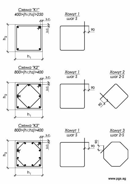
When the ratio of the sides of the section is h1 / h2 \u003d 1 ... 1.5, apply the reinforcement schemes "K1", "K2", "K3".
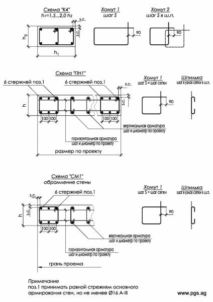
When the ratio of the sides of the section is h1 / h2 \u003d 1.5 ... 2, apply the reinforcement scheme "K4", with a larger ratio, apply the reinforcement scheme for pylons;
For the height of the building, it is recommended to take the column reinforcement scheme constant. It is recommended to adopt the scheme of reinforcement of the columns of the extreme row similar to the reinforcement of the columns of the middle row.
Calculation instructions:
Safety factor (in addition to SNiP) for joint action longitudinal force (N) and bending moment (M) take [k] \u003d 1.4; take [k] \u003d 2 for the action of one longitudinal force;
- When assigning the dimensions of the section, it is recommended to perceive the longitudinal force completely by the concrete body;
When a longitudinal force acts on a column with a small eccentricity e (e \u003d M / N), the column cross-section can only be calculated for the action of a longitudinal force, taking into account the buckling coefficient (table below).
* * *
Design and calculation of walls and pylons
General Provisions:
1. Class (grade) of concrete- not less than B22.5 (M300).
2. Protective layer- 25 mm (for underground structures - 40 mm).
3. Longitudinal reinforcement- A III. The minimum diameter is d12mm. Step no more than 250 x 250 mm
4. Reinforcement percentage- µ \u003d 0.5 ... 2 (for high percentages of reinforcement, the installation of "rigid" reinforcement is required).
5. Transverse reinforcement- d8А I. put in the form of pins in the grid nodes in a checkerboard pattern. on the edges of the walls (pylons), closed clamps are placed with a step s equal to the mesh step (in especially loaded cases, the step of the clamps s \u003d h / 2).
Construction notes:
Minimum wall thickness h\u003e 200 (160) mm;
Wall height to thickness ratio (flexibility) L / h not more than 30;
Reinforce pylons according to the "PN1" scheme, walls according to the "Cm1" scheme;
For the height of the building, the wall reinforcement scheme is recommended to be taken constant.
Calculation instructions:
In view of the designation of sections for structural (architectural) considerations, the safety factor is assumed to be [k] \u003d 1.0;
- In the presence of significant local loads on a section of walls in the body of the wall, form a "hidden" column, or make a pilaster with reinforcement like a column.
* * *
For columns and racks operating in central compression, a square section, sometimes rectangular, circular or annular, is generally accepted.
If the eccentricity is large (as a rule, with eccentric compression), the cross-section of the columns is assumed to be rectangular. In this case, the large sides of the rectangle are located parallel to the axis relative to which there is an eccentricity.
Also, sections can be T-shaped or I-beams.
For the purpose of standardization, rectangular and square sections of columns are taken as multiples of 50 mm.
Concrete for columns is used not lower than B15 (C12 / 15), and for very loaded ones not lower than B25 (C20 / 25).
Columns are reinforced with longitudinal bars of reinforcement with a diameter of ≥ 12 mm made of steel of class A400C or A500C and transverse bars or clamps made of steel of class A240C
The dimensions of the cross-sections should be taken such that the flexibility l0 / r relative to any of the axes of the cross-section does not exceed 120.
The thickness of the concrete cover should be taken ≥ the diameter of the longitudinal reinforcement bars and at least 20 mm. If strip, angle or shaped steel (in columns with a rigid frame) is used as longitudinal reinforcement, the thickness of the protective layer is taken as ≥50 mm;
The clear distance between vertical reinforcement rods, placed vertically during concreting, should be ≥ 50 mm. The distance between the bars of the longitudinal reinforcement, located horizontally or at an angle during concreting, is taken ≥ 25 m for the reinforcement of the lower part of the section and ≥ 30 mm for the reinforcement of the upper part of the section. In addition, this distance is taken in all cases ≥ the largest diameter of the reinforcement;
Cross bars or clamps are installed without calculation, but subject to the following requirements:
If the column cross-section width is ≤ 400 mm and the number of longitudinal bars is ≤ 4, flat welded frames are designed without additional bars or single clamps;
For a cross-sectional width\u003e 400 mm or a number of longitudinal bars\u003e 4, additional bars are installed on one side or double clamps are installed; - instead of double clamps, it is allowed to install connecting pins;
Bendings of the clamps are provided at distances ≤ 400 mm along the width of the element cross-section.
The design of the knitted collars of the columns should be such that the longitudinal rods (at least through one) are located at the bend points of the collars, and these bends - at a distance of no more than 400 mm along the width of the column section. If the width of the edge is not more than 400 mm and the number of longitudinal bars at this edge is not more than four, it is allowed to cover all the longitudinal bars with one clamp.
The distance between transverse reinforcement bars is taken ≤ 15 d for knitted frames and ≤ 20 d for welded frames to prevent lateral buckling of longitudinal reinforcement bars. Moreover, in all cases, this distance is taken ≤ 500 mm, where d is the smallest of the diameters of the longitudinal compressed rods.
In columns with a longitudinal reinforcement coefficient of\u003e 3%, cross bars or stirrups are placed at distances ≤ 10d and ≤ 300 mm.
The diameter of the transverse reinforcement in welded cages is taken:
5-6 mm - with d \u003d 14-20 mm of longitudinal rods;
8 mm - with d \u003d 22-25 mm;
10 mm - with d \u003d 28-32 mm;
12 mm - with d \u003d 36-40 mm;
In knitted frames, the diameter of the clamps is taken as ≥ 5 mm and ≥ 0.25d, in this case d is the largest diameter of the longitudinal reinforcement bars.
As a rule, in the manufacture of knitted frames, clamps of A240C class wire with a diameter of 6-8 mm are used.