The foundation is the most vulnerable part of the design. Due to the fact that the upper part of the building is exposed to the load on the compression, and the lower - on the stretching, the correct base laying plays a big role. To fulfill the correct reinforcement of the ribbon foundation, it is necessary to calculate according to the scheme.
Such a basis is essentially a reinforced concrete strip passing through the outer part of the building and under the bearing walls inside.
In compressions, concrete structures can withstand 50 times more than when stretching. And the upper, and the lower part of the design experiences overload, so it is necessary to perform reinforcement of both parts. On the middle part nothing almost does not have loads. Metal fittings helps solve these problems.
To ensure strength, reliability, durability of the building, any reason must be reinforced. After all, the foundation is subjected to various loads. This is the weight of the whole house, and various soil movements. The ribbon foundation reinforcement scheme resembles a design skeleton, which is assembled from steel rods. In order to choose the necessary scheme for it, it is necessary to understand what it represents.
Reinforcement of the ribbon foundation can be easily done with their own hands, not attracting specialists. It is primarily important to choose the necessary diameter of the reinforcement
Reinforcing material
The choice of material is a fairly important stage. For the reinforcement of the ribbon foundation, with their own hands apply steel rods of different sections or fiberglass fittings. But most often used metal.
The main horizontal fittings has a cross section of rods from 12 to 24 mm. Rods that will be located vertically, which are auxiliary. therefore usually, the cross section of vertical rods from 4 to 12 mm. Such a big difference is due to the scatter in the load on the base and is directly dependent on the type of soil and the weight of the structure.
Auxiliary vertical rods are installed if the foundation height exceeds 15 cm. At the same time, the reinforcement is used by a cross section of 6-8 mm class A1. The frame is collected from rods and clamps, cleaning them from rust. If necessary, the rods straighten and cut. A knitting wire and hook are used as a junction of rods. Welding work can be performed if the "C" marking on the rods.
The choice of diameter affects the number of horizontal levels and the reinforcement scheme of the belt basement.
Calculation of the reinforcement of the belt foundation
 The number of reinforcement elements must be calculated based on the size of the base. For foundations, the width of which is 40 cm. Such 4 longitudinal rods are two top and bottom. To install a row of a frame in a ribbon base, 6x6 m in size will be needed, on average, 24 m reinforcement. If you put 4 bar, you will need 96 m longitudinal rods.
For the across and vertical reinforcement of the foundation, the width of which is 0.3 m and the height of 1.9 m for each attachment with an indentation 5 cm from the surface according to the concrete calculator it is necessary (30-5-5) x2 + (190-5-5) x2 \u003d 400 cm or 4 m reinforcement elements of a smooth form.
If the installation step of the clamp is 0.5 m, the number of compounds will be: 24 / 0.5 + 1 \u003d 49 pcs. It means that based on the calculations, you will need 4x49 \u003d 196 meters of transverse and vertical rods.
The total area of \u200b\u200bthe reinforcement cross sections and its weight, based on the diameter of the rods, can be treated with the table:
Armature diameter, mm |
The calculated area of \u200b\u200bthe transverse rod, mm 2, with the number of rods | Theoretical mass of 1M length of reinforcement, kg | ||||||||
| 1 | 2 | 3 | 4 | 5 | 6 | 7 | 8 | 9 | ||
| 6 | 28,3 | 57 | 85 | 113 | 141 | 170 | 198 | 226 | 254 | 0,222 |
| 8 | 50,3 | 101 | 151 | 201 | 251 | 302 | 352 | 402 | 453 | 0,395 |
| 10 | 78,5 | 157 | 236 | 314 | 393 | 471 | 550 | 628 | 707 | 0,617 |
| 12 | 113,1 | 226 | 339 | 452 | 565 | 679 | 792 | 905 | 1018 | 0,888 |
| 14 | 153,9 | 308 | 462 | 616 | 769 | 923 | 1077 | 1231 | 1385 | 1,208 |
The minimum area of \u200b\u200bthe reinforcement of the foundation is regulated by regulatory documents, and the strength of the foundation depends on
What scheme it is better to choose
There are two main reinforcement schemes that are most often used to strengthen the base for low-rise buildings:
- four twigs;
- six rods.
In accordance with SNiP 52-101-2003, adjacent rods of reinforcement should be located at a distance of 40 cm (400mm) in one row. Extreme longitudinal fittings should be at a distance of 5-7 cm (50-70 mm) from the side walls of the base. Therefore, if the width of the base is more than 50 cm, then it is better to use a six-rod reinforcement scheme.
Depending on this, the diameter of steel rods is chosen.
Usually, laying of "into the cell" rods is used for the ribbon base. In this case, all rods are attached at an angle of 90 °. For longitudinal location, the valves of class A3 are used having a round shape.
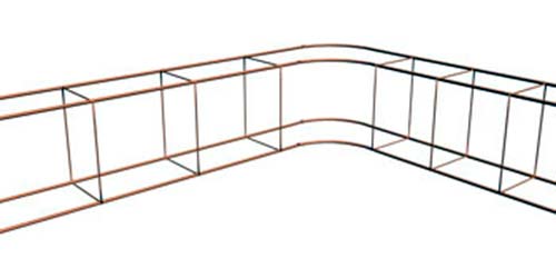
How to rein the corners
At the corners there are a large load. Therefore, during reinforcement, it is necessary to take care of their strengthening.
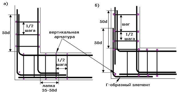 For This should be taken into account the following rules:
- prut must be bent so that one side of his side is plunged into one wall of the foundation, and the second one is in another wall;
- if the rod is insufficient length to make a bend, then for the attachment of rods on the corner you can use M-shaped profiles.
Most often for this is used class A3 fittings.
How to perform reinforcement with your own hands
To do this, you should take a square or a rectangle.
Before installing the frame on the bottom of the trench, you must lay out a sandy pillow with a depth of 1 m.
The frame is set in this way:
- on the bottom of the trench, bricks are placed, the height of which is 5 cm (in order to create a gap between the bottom of the base and the frame);
- to install the racket rods, it is necessary to make a sample in advance, according to which the rods will be cut;
- on bricks, rods of the longitudinal form are laid;
- to the longitudinal rods in 50 cm increments with knitting wire, the horizontal jumpers are tied with a length of a little less than the base thickness (approximately 5 cm on each side);
- the corners of the resulting cells fasten the rods vertically long 10 cm longs are less than the height of the base;
- top longitudinal rods are mounted to vertical reinforcement;
- top transverse rods are tied to the corners.
In the reinforcement of the belt foundation, it is necessary to adhere to the requirements of SNiP 52-01- 2003
The main provisions SNiP 52-01-2003
The main provisions of SNiP 52-01-2003 relate to the distance between the horizontal ribs of the steel frame and the diameter of the reinforcement. So, between the longitudinal rods should not be less than 25 cm and more than 40 cm.
The cross section of the rods is chosen according to the number of longitudinal rods. For a belt foundation, it should be at least 0.1% of the area of \u200b\u200bthe working section of the base. For example, if the foundation height is 1 m, and the width is 0.5 m, the cross-section area should be approximately 500 mm2.
Visually than the minimum diameter of reinforcement can be viewed in the table of examples:
| Terms of use of fittings | Minimum diameter of reinforcement | Regulatory document |
| Longitudinal workforce along the side of 3 meters or less | 10 mm | |
| Longitudinal workforce along the part of more than 3 meters | 12 mm | Reinforcement of elements of monolithic reinforced concrete buildings |
| Constructive fittings | The section is 0.1% of the cross-sectional area at the height of the distance between the armature layers and the half of the ribbon width | |
| Cross fittings (clamps) compressed elements | At least ¼ the largest diameter of longitudinal reinforcement and not less than 6 mm | |
| Cross fittings (clamps) knitted bending frames | not less than 6 mm | SP 52-101-2003 Concrete and reinforced concrete structures without pre-voltage of reinforcement. |
| Transverse fittings (clamps) of knitted frames of the height of section 80 cm and less | 6 mm | Concrete and Concrete Construct Construction Design Guide |
| Clamps of knitted frames of the height of section more than 80 cm | 8 mm | Concrete and Concrete Construct Construction Design Guide |
