4.1.6. Fountain fittings
Fountain fittings refers to well equipment, which is designed to perform the following functions: a) sealing the annular space between the casing and risers; b) the direction of movement of the gas-liquid mixture; c) suspension of downhole equipment; d) creating back pressure at the mouth; e) conducting research, development and other technological operations.
The armature consists of a number of structural elements. The pipe head is used to suspend flow pipes, seal the wellhead, and carry out various technological operations. Includes column flange, pipe head spider, pipe head tee, transfer spool. The fountain tree serves to guide and regulate well production. Includes a central valve, a Christmas tree cross (in the tee fittings of a triple), a buffer valve, a buffer pipe, a union.
Purpose of each of the reinforcement elements: casing flange - for connecting the reinforcement to the casing and sealing the annular space; pipe head cross - for communication with the annular space of the well; pipe head tee - for suspension of the first row of pipes and communication with it; transfer coil - for suspension of the second row of pipes and communication with it; central valve - for closing the well; the tree cross is used to direct the well production into the pipeline; buffer valve - for lowering downhole tools into the well; buffer pipe - for placing instruments before running into the well and reducing pressure fluctuations in the fittings (gas accumulates there); choke - to regulate the flow rate of the well; working monifold - part of the fittings between the fittings and the common flow line, designed to connect two outlets into one; auxiliary monifold - a lily connecting the annulus or tubing and serves to supply air, gas and other agents to the well during technological operations.
The design of the main elements of the reinforcement. The main requirement for fittings is its absolute tightness with high strength of parts, their quick assembly and interchangeability.
Locking devices. Three types of shut-off devices are used: straight-through valves, taps, angle valves.
The choke or choke is designed to maintain the specified operating mode of the wells.
Casing heads are designed to seal the space between the casing pipes run into the well. Different types of casing heads are used depending on the well design.
4.2. Oil production by sucker rod pump installations
Forced lifting of oil from wells using pumps is the longest in the life of a field.
One of the varieties of this method is oil production with sucker rod pumps (SUGP).
The USHGN is a single-acting piston pump, the rod of which is connected by a column of rods with a ground drive - a pumping unit. The latter includes a crank mechanism that converts the rotational motion of the prime mover into a reciprocating motion and imparts it to the rod string and the pump plunger.
The implementation of the method is carried out using the installation, the diagram of which is shown. The underground equipment consists of: tubing, pump, rods, devices for dealing with complications.
Ground equipment includes a drive (pumping unit), wellhead equipment, a working monifold.
The installation works as follows. When the plunger moves up, the pressure in the pump cylinder decreases and the lower (suction) valve rises, opening the access of liquid (suction process). At the same time, the liquid column above the plunger presses the upper (delivery) valve to the seat, rises up and is thrown out of the tubing into the working monifold (injection process).
When the plunger moves down, the upper valve opens, the lower valve is closed by liquid pressure, and the liquid in the cylinder flows through the hollow plunger into the tubing.
Consider the design and operation of individual units of the sucker rod pumping unit.
4.2.1 Drive
Drives are classified: a) by the type of energy used - mechanical, hydraulic, pneumatic; b) by the number of serviced wells - for individual and group; c) by the type of prime mover - into electric and heat.
The pumping unit is an individual drive of a sucker rod pump, which is lowered into the well and connected to the drive by a flexible mechanical link - a rod string.
Structurally, the rocking machine is a four-link mechanism that converts the rotational motion of the prime mover into the reciprocating motion of the rod string.
The device of a serial pumping unit in accordance with GOST 5866-76 is described as follows.
The torque from the electric motor through the V-belt transmission is transmitted to the drive shaft of the gearbox, and then to the driven shaft. On the latter, a crank with counterweights is fixed. The crank with the help of connecting rods and a traverse is connected with a balance bar swinging on a support fixed on a rack. The balancer on the side of the front shoulder is equipped with a folding head on which the rope suspension is mounted.
The rocking machine (SK) consists of a number of independent units.
The frame is designed for installation of all SC equipment on it and is made of rolled profile in the form of two runners connected by cross-sections, and has a special stand for the gearbox. The frame has holes for fastening to the foundation.
The rack is a support for the balancer and is made of rolled profile in the form of a four-sided pyramid. The legs of the rack are interconnected by crossbars. From below, the stand is attached to the frame by welding or bolts, from above it carries a plate for attaching the axis of the balancer using two brackets.
The balancer is designed to transfer the reciprocating motion to the rod string. It is made of profile rolled I-section and has a single-girder or double-girder construction. From the side of the well, the balancer ends with a swivel head.
The balancer support is an axle, both ends of which are mounted in spherical roller bearings located in cast iron housings. A bar is welded to the middle part of the axle, which has a square cross section, through which the balance bar support is bolted to the balance bar.
The traverse acts as a connecting link between the crank mechanism and the balancer and is structurally made in the form of a rectilinear beam made of profiled steel. Fastening to the balancer is articulated with a spherical roller bearing.
Connecting rod - pipe billet with special heads at the ends; with the help of the upper head, the connecting rod is connected with a pin to the crosshead, the lower one is connected with a crank through a pin and a spherical bearing.
The crank is the main element of the crank mechanism designed to convert the rotary motion of the gearbox shaft into reciprocating rods. It is made in the form of rectangular plates with holes for attachment to the connecting rods and the driven shaft of the gearbox. Equipped with grooves for mounting and moving counterweights.
The rope suspension is a flexible link between the rod string and the balance bar. Consists of two traverses - upper and lower, separated by cable clamps bushings. On the upper traverse there is a polished rod fastening assembly. The traverses can be pushed apart with screws to mount the dynamograph.
V-belt transmission SK provides for the use of V-belts of types O, A, B, C, D. Choosing the correct belt type ensures the longevity of the transmission.
The pulleys are quick-changeable due to the tapered bore of the body and the use of a tapered sleeve secured with a nut.
The swivel carriage is a frame for the engine that is mounted in an inclined position, which provides a change in the center-to-center distance between the axes of the shafts and, therefore, tension on the belts.
A double shoe brake is mounted on the brake drum and driven by a lead screw. For safety reasons, the brake handle is placed at the end of the rocker frame.
The drive of the pumping unit is a three-phase, asynchronous electric motor in a moisture-freeze-resistant design with a squirrel-cage rotor with multiplicity of starting and maximum torque 1.8 ... 2.0 and 2.2 ... 2.5, respectively.
The main synchronous speed is 1500 rpm. To obtain the required number of strokes of the suspension point of the rods, electric motors with a speed of 750 or 1000 rpm of the AOP series can be used.
In addition to the described drive, which is based on an oscillating balancer, several designs without balance drives have been created and used in the Russian Federation and abroad. The advantages of these actuators are reduced overall dimensions of the actuator, improved service conditions and reduced metal consumption, increased portability and installation ability.
The principal distinctive feature of all non-balancing SCs is the absence of a swinging balancer.
An example of a non-balanced mechanical drive is the following design. It consists of a support boom, at the upper end of which there is a double sprocket and roller chains. The ends of the chains are attached to the traverse. Connecting rods are attached to the latter. The gearbox is driven by an electric motor. V-shaped with holes for connecting rods are mounted on the driven shaft of the gearbox. Counterweights are installed on the circumference of the disc.
Several types without balancing drives are used abroad, one of the varieties of which is the following. It consists of a steel truss installed at the wellhead. On the upper platform of the farm there is a drive motor with reversible gearboxes, on the output shaft of which a pulley is fixed. A balancing weight is thrown over the pulley from the side of the farm, on the other - a rope with a polished rod. The truss is installed on rails and can be rolled back during underground repairs. The reversible gearbox is controlled by the control panel: when the polished rod reaches the extreme positions, the control panel gives a command to change the direction of rotation.
Such SCs are produced in the USA by the Oil Val company and have the following characteristics: stroke length up to 10.2 m, carrying capacity up to 157 kN, number of strokes up to 2 min-1, power up to 30 kW.
The hydraulic drives of sucker rod pumps have been used abroad. They include a lifting cylinder, a balancing cylinder, interconnected by a system of oil lines. The hydraulic power section consists of a pump and a switchgear. The pump pumps oil into the lift cylinder, causing the piston and then the rod string to rise. In the upper position, the distributor is triggered and oil flows out from under the piston.
The balancing of the hydraulic drive occurs by the flow of oil from the sub-piston cavity of the cylinder during its downward movement into the sub-piston cavity of the cylinder and the rise of its piston. Then, during the upward stroke, the reverse process occurs: oil from under the piston cavity of the cylinder flows into the subpiston cavity of the cylinder, helping to move its piston upward.
And microorganisms. The soil is usually self-cleaning very slowly through the biodegradation of oil. Studies of soil properties made it possible to draw certain conclusions about the nature and degree of disturbance of the ecological situation, depending on the amount of petroleum organic matter entering the soil. With a content of 20-100 t / ha of petroleum organics in the soil, the vital activity of all is stimulated ...
On concessions and production sharing agreements, oil companies acquire ownership of a portion of the produced product, respectively, at the wellhead and destination of the product. Chapter 2. International legal mechanism for the exploitation of hydrocarbon deposits: problems and solutions 2.1 Legal substantiation of payment for the operation of hydrocarbon deposits ...
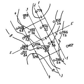
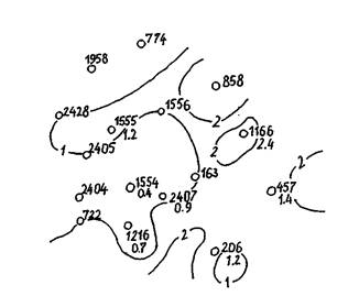
Formation (0 0) The design of well # 1554 is presented in Table 28. For the projected well # 1554, select an S-shaped profile. This profile of a directional well is used in cases where the opening of a productive object is provided for by a vertical wellbore. Table 28. Design of well No. 1554 of the Tuimazinskoye field Casing string Nominal diameter, mm ...