The corners and adjoining of the belt foundation are places of concentration of multidirectional stresses. Incorrect docking of the longitudinal working reinforcement in the areas of the adjoints and in the corners can lead to the appearance of transverse cracks, bundles and openings in these problem areas. The correct reinforcement of the belt foundation ensures the resistance of the reinforced concrete structure to the forces of compression and stretching in all its sections.
Fig.1. Loads at the end of the foundation.
General rules for applying fittings in the construction of belt foundations are set forth in. In paragraph 8.9 of this document it is indicated that the foundations of the walls should be combined into the system of cross-tapes and have a rigid bundle. The methods of hard connection of the reinforcement says. In paragraph 8.3.26, all allowable methods of such compounds are listed:
1. Docking reinforcement without welding, brace. The following methods of anchoring are allowed in the Ostlenka area: with direct ends of corrugated reinforcement, with welding transverse rods, with bends at the ends in the form of hooks, or loops.
2. Welding of reinforcement.
3. Application of mechanical devices, or threaded couplings.
The rigidity of the armature connection on the corners, or the adjoits can only be provided with these methods. Compounds with the help of a mating of the crosshair during the reinforcement of the corners of the ribbon foundation are not allowed. In this case, the angular rupture of the reinforcement frame and the loss of its integrity occurs. To enhance the angular reinforcement joints, it is possible to use P-and M-shaped elements made from reinforcement rods used for the device for longitudinal (working) reinforcement. Vertical and transverse clamps in the field of angular and adjacent anchors are set 2 times more often than in the rest of the belt foundation. The optimal distance between the clamps in the zones of adjoins and angles is defined as half of the tape height. It is not recommended to do this distance of more than 25 cm. For a uniform distribution of loads on the corners of the ribbon, as well as in the field of adjoints, a rigid bunch of internal and external longitudinal reinforcement is made.
Corners and adjoint reinforcement schemes
To form a single rigid spatial frame of the ribbon foundation, the following circuits of angular and adjacent connections of longitudinal reinforcement are used:
1. Hard angular connection of the reinforcement of the venge and the "paw".
2. Reinforcement of the angular zone using a g-shaped clamp.
3. The coal reinforcement scheme with a P-shaped clamp.
4. Reinforcement of the adjoining zone using a compound of the Van.
5. The scheme of reinforcing the adjacent zone with the help of a g-shaped clamp.
6. Reinforcement of the field of adjoining with the help of a p-shaped clamp.
7. Reinforcement of stupid angles with the help of a rigid connection.
Any of the above proper schemes provides a hard compound of the internal and external longitudinal reinforcement.
Reinforcement of the angular zone with the help of tight compounds of the brass and "paws"
1. The rigidity of the angular connection of the external horizontal reinforcement is ensured by a flavor with a bend of one of the free ends (1-2).
2. Binding internal horizontal reinforcement (7) to external horizontal fittings (2) is carried out.
3. The binding of the inner horizontal fittings (3) to the outer conjugation (1-2) is performed using the "foot" connection.
4. The step of the angular transverse fittings (5) and the vertical fittings (4) is calculated by the formula 3/8 of the height of the tape base.
5. The length of "foot" is 35-50 diameters of longitudinal reinforcement.
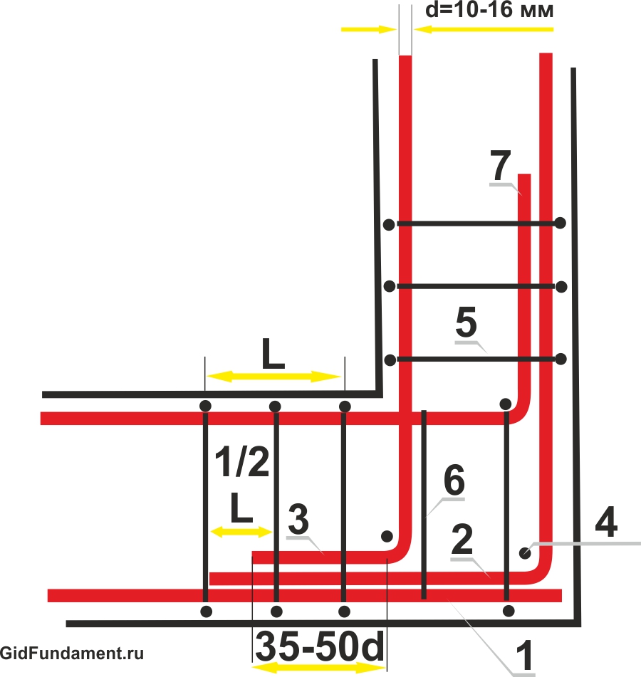
Fig. 2. Scheme of reinforcement of the corner of the tape basement.
Reinforcement of the angular zone of a belt foundation using a g-shaped clamp
1. The stiffness of the connection of the external longitudinal reinforcement (1) in the angular zone provides a M-shaped clamp (6).
2. Internal longitudinal fittings (2) is hard to fasten with the outer longitudinal reinforcement (1) of the Van.
3. The transverse reinforcement step (L) is no more than ¾ the height of the foundation tape.
4. Internal and external longitudinal reinforcement connects additional transverse fittings (5).
5. The length of the compound of the cell is 50 diameters of horizontal reinforcement.
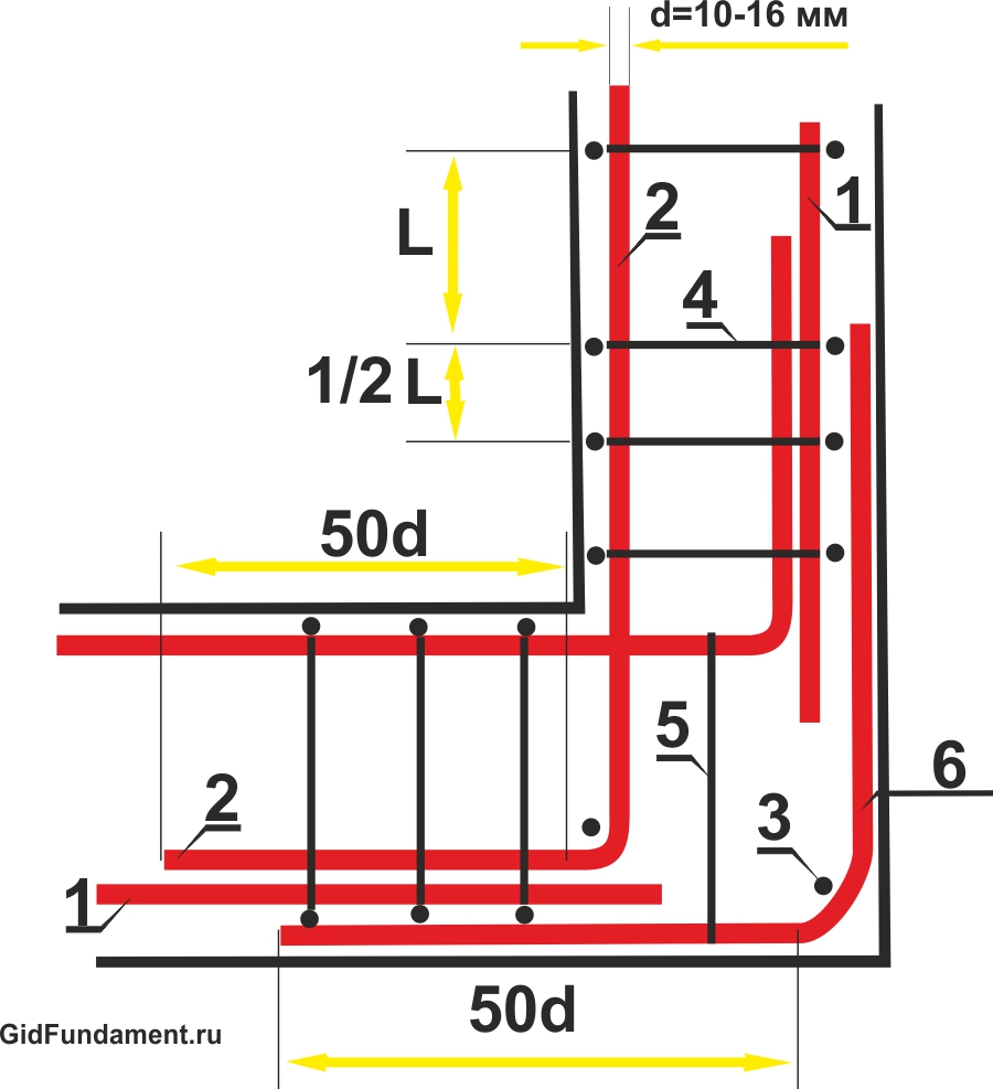
Fig. 3. The scheme of reinforcing the angle of the ribbon foundation M-shaped clamp.
Reinforcement of the corner of the ribbon foundation using a clamp of the P-shaped
1. When using P-shaped clamps (5), the angular connection of the outer and internal horizontal reinforcement of the ribbon foundation (1) gets a hard curl like a lock.
2. Vertical (2), transverse (3) and additional transverse (4) fittings are involved in the anchoring of P-shaped clamps.
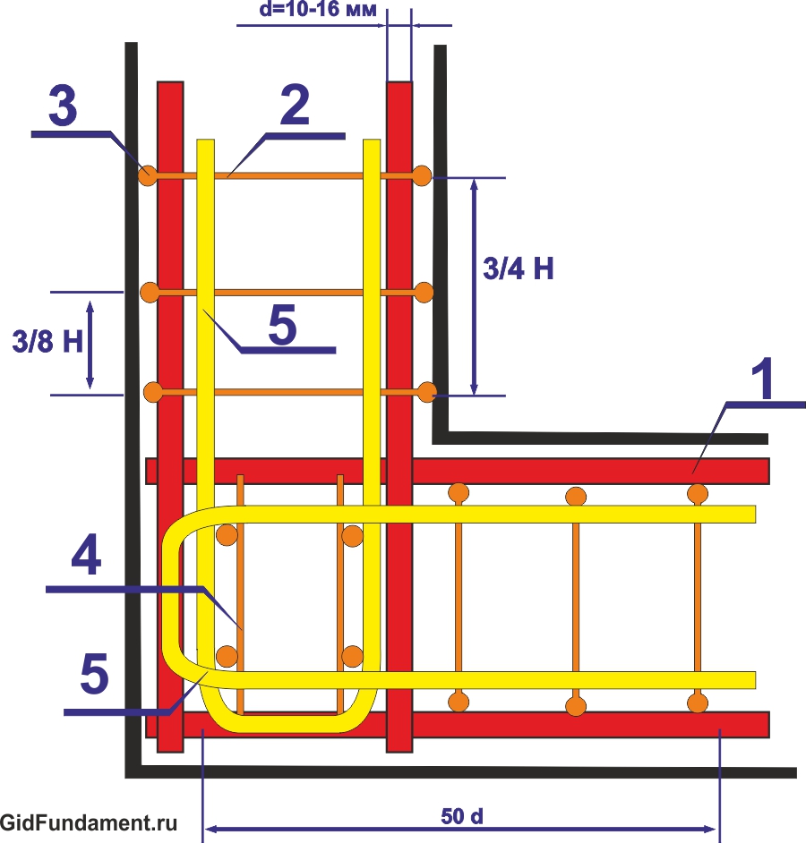
Fig. 4. The scheme of reinforcing the corners of the ribbon foundation P-shaped clamp.
Reinforcement of the pricing zone with a compound of the Van
1. The compound of the horizontal fittings (2) of the adjacent element of the belt basement is carried out only to the external horizontal fittings (1).
2. The transverse (4) step (4), additional transverse (5) and vertical fittings in the adjoining zone should be at least 3/8 from the height of the foundation tape.
3. The sizes of the compound of the camuralist are 50 diameters of the working reinforcement.
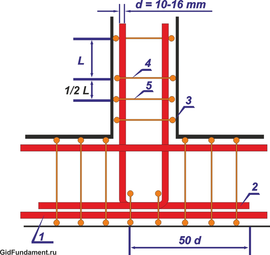
Fig.5. The scheme of reinforcement of the ribbon basement of the bang.
Reinforcement of the pricing zone using a g-shaped clamp
1. When using a M-shaped clamp (6) for reinforcing the adjustment zone, the horizontal fittings of the adjacent part and the external horizontal fittings (1) are connected to the corner of the Van.
2. The length of the compound of the cell (2) is 50 diameters of the working fittings.
3. The step of vertical (3) and transverse reinforcement (4) in the adjoining zone is reduced by two times with additional transverse reinforcement (5).
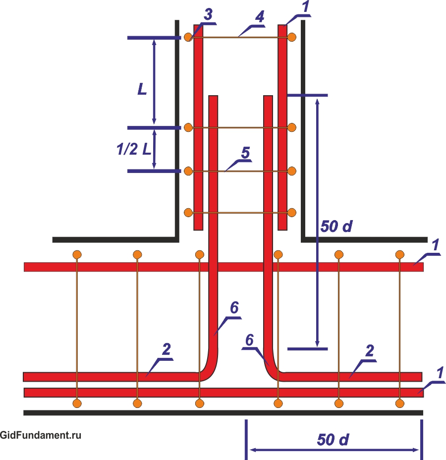
Fig. 6. The scheme of the reinforcement of the ribbon basement of the g-shaped clamp.
Using a p-shaped clamp for reinforcing a ribbon base adjustment zone
1. The p-shaped clamp (6) provides an additional rigid binding of the horizontal fittings of the adjacent element of the belt basement (3) to the outer horizontal fittings (1).
2. The length of the compound of the cell (2) can be 35-50 diameters of horizontal fittings.
3. The minimum permissible length of the P-shaped clamp must be equal to the double width of the belt foundation.
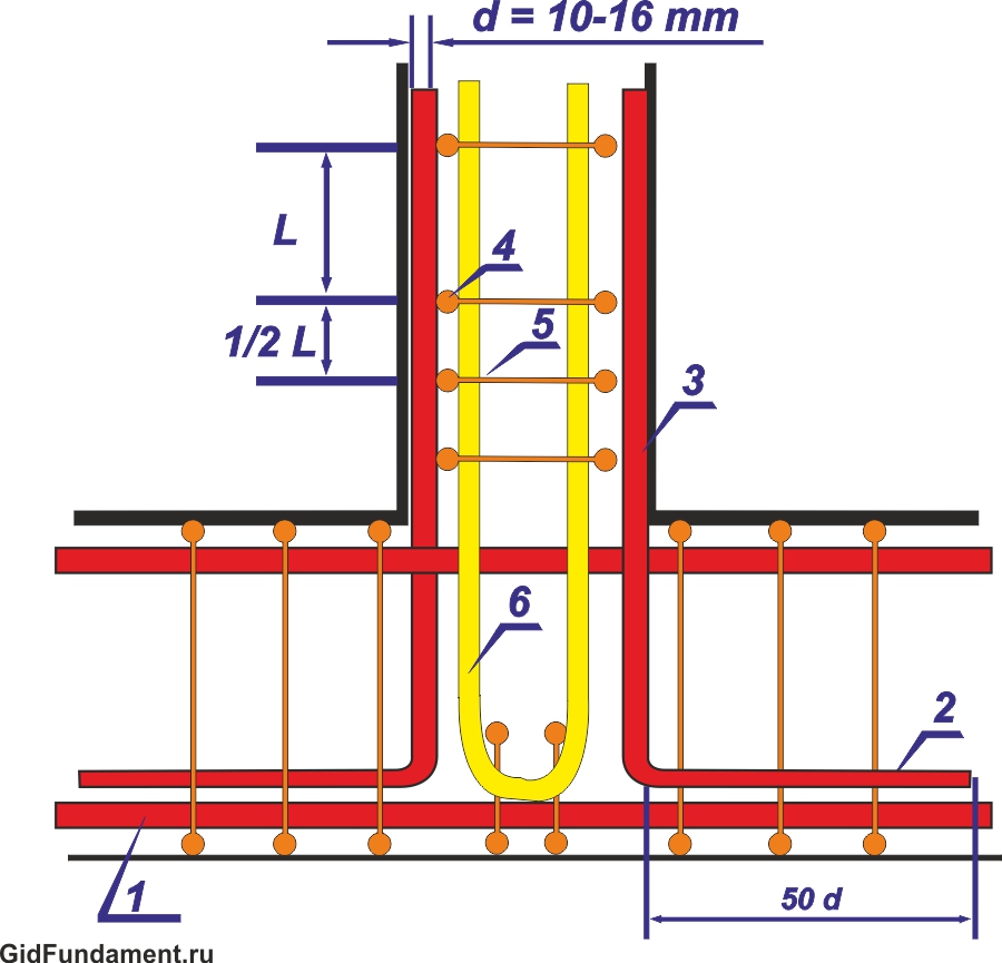
Fig. 7. Scheme of reinforcement of the ribbon foundation of a g-shaped clamp.
Reinforcement of the brand of stupid angular connections of a tape foundation
1. For a reliable compound of the reinforcement frame, when the ribbon foundation is rotated under a stupid angle (1), a diagram of a hard compound of the flask of the free ends of the inner horizontal fittings (4) with an external horizontal reinforcement (5) is used.
2. Vertical (2) and horizontal (3) reinforcement in the connection zone of the flask should be set 2 times more often than on smooth ribbons.
3. The length of the compound of the flask must be at least 50 diameters of the longitudinal reinforcement.
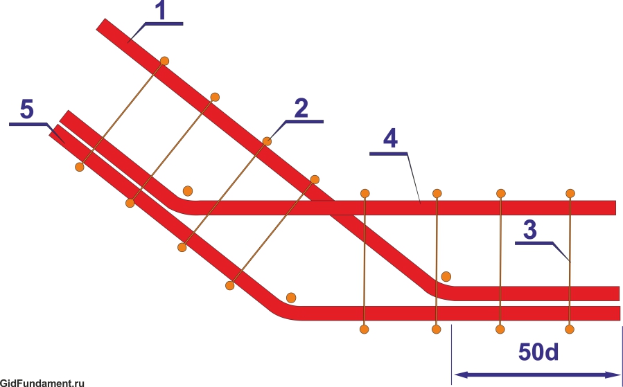
Fig. 8. Scheme reinforcement of a stupid angle of a ribbon foundation.
Typical errors in the reinforcement of angles and adjoins
All the correct methods of angular and adjacent reinforcement compounds used in the construction of a belt foundation are aimed at maintaining the integrity of the reinforcement frame, regardless of its configuration. The strength of the belt foundation depends on the correct anchoring of the terminal elements of the longitudinal reinforcement. The following schemes lead to incorrect reinforcement of corners of the ribbon foundation:
1. Reinforcement of angular zones of ribbon foundation by reinforcement crosses with a viscous rods of longitudinal reinforcement under right angles.
2. Installation in angular and adjacent zones of bent longitudinal reinforcement without anchoring.
These errors are the most common and can lead to the destruction of the foundation in the places of angular compounds and adjoints.
Corner and adjoining compounds made by mating crosses of longitudinal reinforcement rods
1. The terminations of the longitudinal fittings (1) are directed at each other to each other, do not form a rigid coupling and cannot resist stretching arising due to loads in the middle part of the tape base.
2. The elements of the transverse (3) and vertical fittings have only a structural function.
The typical error of the reinforcement of the angles and the adjoints is the connections of the longitudinal reinforcement by the method of viscous crosshairs. Such a reinforcement compound without proper anchoring of rods can lead to the destruction of concrete monolith due to multidirectional loads arising from the corners of the ribbon foundation.
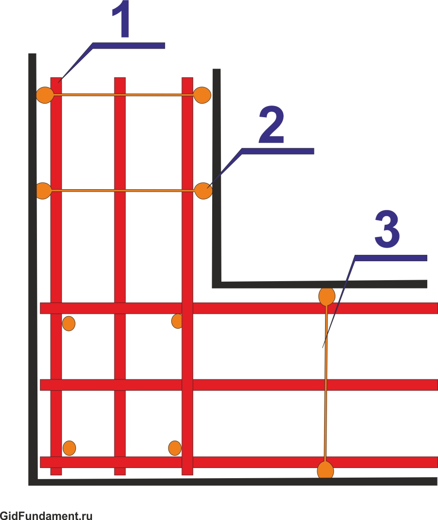
Fig. 9. Frequent error in the reinforcement of angles
Application of bent longitudinal reinforcement for reinforcing angular compounds and adjoins
1. Angle compounds without a bundle of internal and external longitudinal reinforcement (1) do not provide rigid rod fixation.
2. The destruction of the foundation can occur not only due to the formation of transverse cracks, but also due to peeling inner angles.
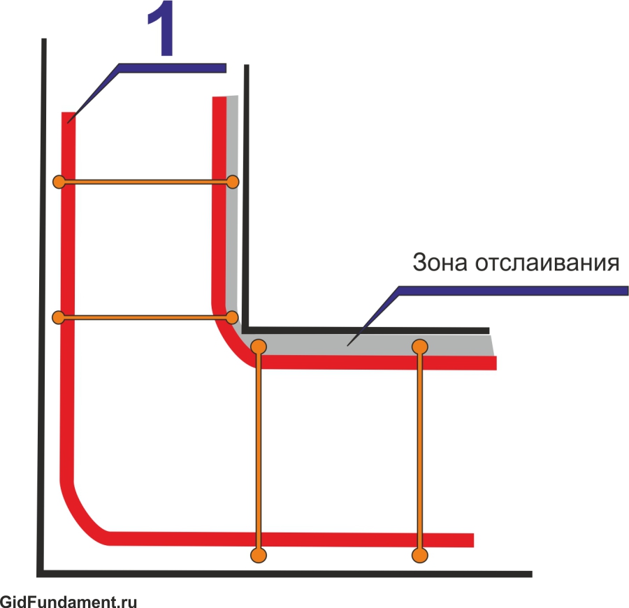
Fig. 10. Another example of improper reinforcement of angles
In order to prevent the appearance of cracks, openings and bundle on the corners and adjoins of the belt foundation, it is necessary to properly connect the terminal rods of the longitudinal reinforcement and perform their reliable anchoring. The correct reinforcement of the corners of the belt foundation is the key to the reliability and durability of the building.
Tip! If you need contractors, there is a very convenient service for their selection. Just send in the form below a detailed description of the works that you need to perform and offers to you in the post office with prices from building brigades and firms. You can see the reviews about each of them and photos with examples of work. This is free and does not oblige anything.