Welded joints are a continuous sealed splicing of two metal elements. The type and design of the weld is determined by the relative position of the parts relative to each other.The properties of the base metal and the requirements for the strength of the structure determine the welding method (arc, contact). Let us consider in detail what designs of seams are used when welding various surfaces.
Kinds welded joints: a - butt; b - butt flanged; c - overlapping; g - corner; d - T-shaped; e - slotted; w - end; h - point; S is the thickness of the products to be welded.
Types of welded structures and their designation in drawings
Depending on the spatial arrangement of the planes relative to each other, the following types of welding are used:
- Joint: the planes to be welded are butt-welded, butt-ends, while they are on the same surface.
- Overlap: the surfaces are located in close planes, parallel to each other, when welding they partially overlap each other, forming an overlap.
- Angle: The planes are connected at an angle.
- T-shaped: the end of one element is attached to the side surface of the second weld part, thus forming a T-shaped joint, which is called a T-joint.
- End: two elements are placed side by side (side by side) and their ends are welded with one seam located along the common end.
Designation welds in the drawing: a, b - visible seam - main line; b - visible single welded point - “+” sign; d - invisible seam - dashed line
Welds in the drawings are indicated by a line (if the seam is solid) and crosses (if it is a point). The presence of welding in the structure is indicated by a one-sided arrow with a leader, which indicates the letter designation of the seam. Butt and end connections are conventionally designated by the letter "C", overlap - "H", corner - "U" and T-shaped - "T".
If the seam is located on the visible side of the part (this side is shown in the drawing), then it is called "visible", denoted by a solid continuous line and information about it is located above the leader line. If it is located on the back side, it is called invisible, denoted by a dash-dot line and an alphabetic display is applied under the extension line of the one-sided arrow.
Spot welding is indicated by a cross.
Technological features of welded seams
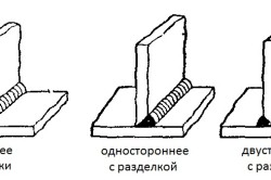
Metal welding often requires technological preparation of elements. It consists in cleaning the surface and performing the so-called grooving (beveling of the edges).
Bevels can be made on both edges or on one, one or two sides of the ends to be welded. The process of making bevels is called cutting.
In cases where the cutting operation is absent in the manufacturing technology of the object, the welding current must be increased to penetrate the joint.
Pre-cutting is most relevant for the butt arrangement of elements in electric arc welding.
Butt welding
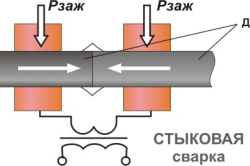
Butt welding is the most durable type of joint. The edges are connected over the entire area of \u200b\u200btheir contact, which ensures the highest possible strength.
Butt welding can be carried out both by the arc method (with an electrode deposited with an electric arc) and by contact fusion without an electrode. For arc welding of structural parts, their preparation is necessary. It consists in making bevels of right angles. In the place of the bevel, a seam zone is formed, consisting of an electrode filler material (mainly outside) and a base metal (mainly inside).
If the ends of different thicknesses are welded, then the bevel is made at the thicker end in order to equalize the thickness of the surfaces to be joined in the welding zone and eliminate burn-through of a thinner element.
Cutting edges is not always technologically possible. Then the operation is performed without preliminary bevels by the contact method. According to the technology of contact welding, the parts are heated until they are melted by an electric current (passing through them), after which they are squeezed for tight contact of the surfaces. In this case, strong interatomic bonds are formed between the two metal elements. Excess liquid metal, squeezed out from the fusion zone by squeezing the contacting surfaces, is removed before solidification. This method is called flash welding.
There is and is used another method of making a joint, called resistance welding. It is used only for parts of small cross-section and requires preliminary cleaning of the places of future contact. The technology for its implementation is as follows:
- parts bring together and squeeze;
- let the welding current pass and heat up the metal elements, while the small size of the contact section ensures uniform heating of the metal;
- splicing of parts is carried out without reflow, in the solid phase.
Resistance butt welding is characterized by increased strength due to the absence of flashing. It does not form an accelerated cooling structure in the seam zone, does not create a wide heat-affected zone (with reduced strength), and forms a smaller amount of residual stresses.
Overlap construction
An overlap is often used to connect elements in assembly and installation. It does not require preliminary preparation, beveling. When overlapping, welding can be performed with one or two seams: along the edge of one or the second surface to be welded, or along both edges. The advantages of an overlapping welded structure are the low likelihood of through burn-throughs and simple technological implementation. The resulting seam has a double thickness (compared to the butt joint), separated by a through slot. When combining parts, inaccuracies and small shifts are allowed, overlapped by the existing overlap.
Overlapping welding has three disadvantages:
- insignificant waste of material: excessive thickness of material in the overlap zone;
- the presence of an empty space between two welded seams requires high-quality penetration from both seams (to prevent moisture from entering the gap);
- the overlap construction is inferior to the butt joint in strength.
When parts overlap, they are penetrated in the corners between the end of one part and the side of the other, therefore, the technology for performing the overlap is determined by the methods of welding the corners.
Fillet welds: varieties of welded corner structures
There are about a dozen types of welded corners, their design is determined by the relative position of parts, the length of the seam, the shape of the edge and its preparation.
Corner splicing is intended for constructive joining of parts, it does not carry significant loads. The joint angle of the surfaces to be welded determines the location of the weld (from the inside of the corner, outside or on both sides).
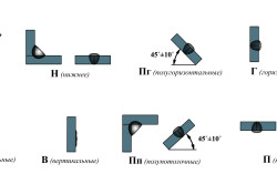
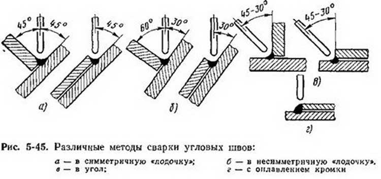
The corner technique is the most difficult, requiring skill and experience. The surfaces to be welded can be located in the vertical-horizontal directions, or in the diagonal-diagonal directions. With a diagonal arrangement, the welding technique is facilitated and accessible to the novice welder. When welding vertical and horizontal, welding becomes more complicated and requires a qualified approach to its implementation.
Fillet welds can be made in one layer or in several layers. In a single layer bonding, one layer is formed from the electrode additive material and the molten base metal. A multi-layer construction is necessary to ensure that there is no lack of fusion when the gusset is complicated by the inaccessibility of the welded surfaces. The possibility of lack of penetration increases with the vertical arrangement of one of the elements, which contributes to the flow of molten metal downward and displacement of the weld pool from the welding zone with the subsequent formation of a void (lack of penetration). Therefore, when connecting parts in the vertical - horizontal planes, a multilayer is provided. Moreover, if the weld spot after cooling has a convex surface, increased thickness, then this adds additional strength to the joint.
Preparing fillet weld surfaces involves beveling (or beveling) one or both elements.
Tee welding
The tee structure is a kind of corner. In this case, in both corners to be welded, welding is performed along the inner corner.
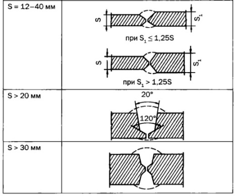
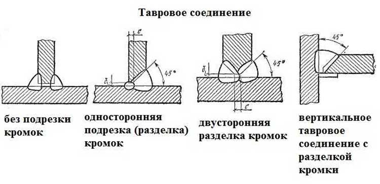
For a T-joint, one of the parts is placed horizontally, the second vertically. The welded element lies horizontally, to whose side surface the end of the other element is welded. The connection angle is always 90º. For a high-quality tee seam, a bevel (one or two) is made at the end of the welded element. If the end is thin (up to 12 mm), bevel is not necessary. If the thickness of the end is 12 - 40 mm, the bevel is made on one side. If the element thickness exceeds 40 mm, then a double-sided butt groove and two welds are required.
Technological implementation of welded tee-welding is similar to welding of a corner from the inside. Thin-walled parts are connected in a horizontal and vertical arrangement of the connected planes. Thick-walled parts, for which electrodes of increased thickness are used, forming a significant weld pool, are placed diagonally. To do this, first, spot welding is performed between the vertical and horizontal parts, then they are rotated, placing the surfaces to be welded in a diagonal direction. In this case, the welded pool is in the "boat", does not spread and forms a high-quality welded joint. In some cases, when not great thickness vertical element, its full penetration occurs.
Weld shape and bevel
In external shape, the seams can be convex, even and concave. Smooth and concave joints are considered economical and more durable (there is no abrupt transition between the base and the thermal zone, there is no stress concentrator that promotes destruction). Often, for critical parts, the formed bulge is removed mechanically (grinded).
The shape of the weld depends on the selected geometric dimensions of the connection. Namely:
- the size of the gap between the parts to be welded;
- the presence and number of bevels of the edges;
- bevel angle of the edges of the surfaces to be welded.
Bevels are performed for parts with a thickness of more than 3 mm, in order to uniform penetration over the entire section. The presence of bevels along the edge of the surfaces to be welded ensures better welding, the presence of a smooth transition from the seam through the welding zone to the base metal. The larger the bevel angle, the wider its plane, the smoother the transition between the welded structure of the seam and the unstressed structure of the metal of the part.
The difference in welded structures allows you to choose the optimal welding parameters, location and method of execution. The welding method used must ensure the required quality of the joint at the lowest possible cost.
The quality of the welding determines the performance characteristics of the finished product.
Weld seams are heterogeneous in structure and include the following zones: base metal, weld, fusion and heat affected zones.
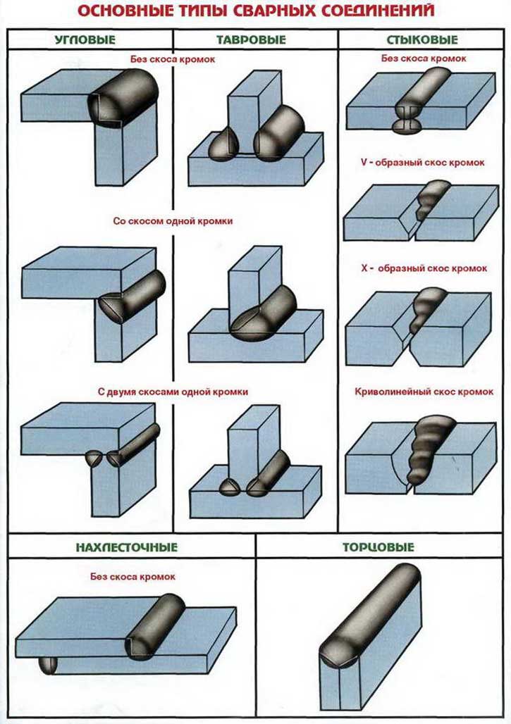
There are the following types of welding joints:
1) Butt.
This is the most common type of joints for various welding methods, which has a number of advantages over others: high welding productivity, minimization of the consumption of welded and deposited metal, high strength with proper adherence to welding technology, and the absence of its own structural stresses. Moreover, such joints require careful preparation of the edges and the accuracy of the relative position of the edges of the parts during assembly for welding.
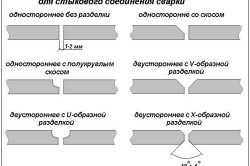
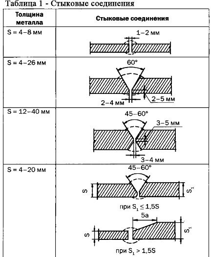
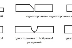
Grooving can be different, examples are shown in table 1.
With a large thickness of edges, a bowl-shaped groove is used, for a thickness of 20 ... 50 mm - one-sided, over 50 mm - two-sided. Butt joints are widely used in welding sheets, pipes, and high-quality metal products.
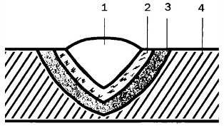
Figure: 1. Zones of the welded joint: 1 - welded seam, 2 - fusion zone, 3 - heat-affected zone, 4 - base metal zone
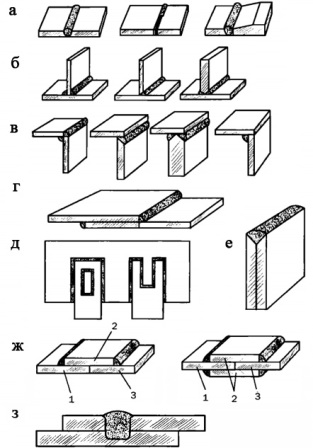
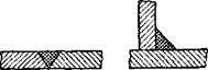
Figure: 2. Types of welded joints: a - butt, b - tee, c - corner, d - overlap, e - slotted, g - with overlays, h - with electric rivets, 1 ... 3 - base metal, 2 - overlap, 3 - electric rivets
2) Corner.
Examples of corner joints are shown in Fig. 2, c. They can be single-sided or double-sided to increase strength. They are also used for welding sheet, shaped and pipe blanks. The angle of inclination of the workpieces can be different, preliminary cutting of edges is required.
3) Taurus.
The vertical T-joint must have a cut edge. It is recommended to bevel on both sides, if penetration is impossible - only on one side. In this case, a gap must be provided between the vertical and horizontal parts for boiling through the entire thickness of the sheet. Tavr is used to connect sheet blanks.
4) Overlapping.
Such joints are mainly used in spot and resistance welding, since in other cases the consumption of the base and electrode metal is unjustifiably increased. In the case of a lap joint, bevel grooving is not required, but they must be cut. To avoid corrosion between the sheets, it is recommended to weld the joint on both sides.
5) End.
In this embodiment, the sheets are stacked on top of each other in the form of a "sandwich" and welded along the common ends.
6) Slotted.
They are used when it is necessary to strengthen the lap joint. The slot is made in an open or closed version.
7) With overlays.
Such joints are also used as an option for reinforcing butt or overlap joints. An example is the use of reinforcing rings on the inner surface during the assembly and welding of tank shells.
8) With electric rivets.
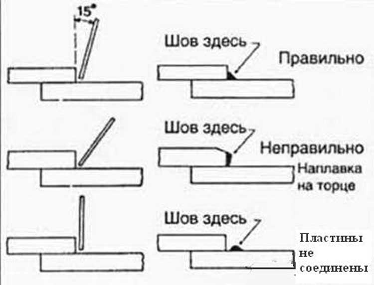
Welding provides permanent joints of metals by establishing strong interatomic bonds between elements (when they are deformed). What are welders, experts know. The seams obtained with their help are capable of joining identical and dissimilar metals, their alloys, parts with additions (graphite, ceramics, glass), and plastic.
Basis of classification
Experts have developed a classification of welds according to the following principle:
- the way they are performed;
- external characteristics;
- the number of layers;
- location in space;
- length;
- appointment;
- width;
- conditions of functioning of welded products.
According to the evaluation of the method of execution, welds are one-sided or two-sided. External parameters allow them to be classified into reinforced, flat and weakened, which experts call convex, normal and concave. The first species are able to withstand long time static loads, but they are not economical enough. Concave and normal joints withstand dynamic or alternating loads well, since the transition from metal to seams is smooth, and the risk of stress concentration that can destroy them is below 1 indicator.
Welding, taking into account the number of layers, can be single-layer or multi-layer, and according to the number of passes, it can be single-pass and multi-pass. Multilayer solders are used for working with thick metals and their alloys and, if necessary, reducing the heat affected zone. A pass is called the movement (1 time) of a heat source in the process of surfacing or welding parts in one direction.
A bead is a piece of seam metal that can be welded in a single pass. The weld layer is a metal junction with several beads located at the same level of the cross section. Focusing on their position in space, the seams are subdivided into lower, horizontal, vertical, "boat", semi-horizontal, semi-vertical, ceiling, semi-ceiling. The characteristic of discontinuity or continuity speaks of length. The first types are used for butt seams.
Classification principles
Solid connections can be short, medium and long. Allocate sealed, durable and strong seams (according to their purpose). Width helps to categorize them into the following types:
- broadened, which are made with transverse, oscillatory movements of the electrode;
- thread, the width of which may slightly exceed or coincide with the diameter of the electrode.
The conditions in which the welded products will be used in the future assume that the joints can be working and non-working. The former carry loads well, while the others are used to join parts of a welded product. Welded joints are classified into transverse (in which the direction is perpendicular to the axis of the seam), longitudinal (in a direction parallel to the axis), oblique (with a direction placed at an angle to the axis) and combined (the use of transverse and longitudinal seams).
The method of holding the hot metal allows you to subdivide into created:
- on remaining and removable steel supports;
- without additional linings, pillows;
- lined with flux-copper, copper, asbestos or ceramics;
- on gas and flux cushions.
The material that is used in the process of welding elements is classified into compounds of non-ferrous metals, steel (alloyed or carbon), vinyl plastic and bimetals.
Depending on the location of the parts of the products that are to be welded relative to each other, there are joints at right angles, at a blunt or acute angle and located in the same plane.
Permanent joints that arise when using welding are:
- angular;
- butt;
- t-shaped;
- overlap or end.
Corner views are used during construction work. They involve a reliable connection of elements that are located in relation to each other at a certain angle and are welded at the junction of the edges.
Butt types have found application in the welding of tanks or pipelines. With their help, parts are welded with ends that are located on one surface or in one plane. The thickness of the surfaces does not have to be the same.
Overlapping types are used in the manufacture of metal containers, in construction work and when welding tanks. This type assumes that one element is superimposed on another located in a similar plane, partially overlapping each other.
The quality of the welded joint directly depends on the type of the selected seam, electrode and operating mode of the device. For this, it is recommended to be guided by the current standards, and in particular - GOST 5264-80. It details the characteristics and types of welds and types of welds. According to GOST, special requirements are imposed on the performance of work.
Butt
The most popular type of connection, as it is characterized by the minimum metal stress, ease of execution and reliability. Depending on the thickness of the edge to be welded, it can be cut at right angles or bevels. It is also permissible to use a one-sided bevel.
Advantages of butt welds:
- the minimum consumption rate of the base and welding metal;
- optimal welding time;
- good quality connections.
The latter is achieved only if the technology is observed. The bevel angle can be varied from 45 ° to 60 °. It depends on the thickness of the metal. A similar geometry is used for sheets of 20 mm or more. The characteristics of the material are also taken into account.
Overlapping
The formation of a joint by overlapping sheets is relevant for metal thicknesses ranging from 8-12 mm. At the same time, unlike butt welding, there is no need to process the surface - it is enough to cut the workpiece evenly. It is important to correctly calculate the amount of overlap.
Features of the lap welded joint:
- increased consumption of the main and deposited material;
- a seam is formed between the surface of one sheet and the end of another;
- field of application - spot, roller and resistance welding.
Before starting work, the sheets must be aligned to ensure a tight hold.
Taurus
This is a T-shaped joint, in which the end of one of the sheets is welded to the plane of the other. For reliability, one or two-sided bevels can be made on the first. With their help, the volume of the deposited metal is increased. Scope - metal structures of complex shape.
Before starting work, you need to consider the following factors:
The bevel configuration is standard, the angle depends on the thickness of the metal.
Corner
They are used to connect two structural elements at a certain angle. In contrast to the T-joint, the presence of a gap is unacceptable. Reliability is provided by bevels and a large volume of directional metal.
Specificity of fillet welds:
- surface preparation is necessary - the formation of bevels of a simple or complex configuration;
- for thin-walled workpieces, one-sided connection is allowed;
- the geometry of the weld is taken into account.
This method is most often used for the manufacture of tanks or structures similar to them in shape.
Auxiliary welds
In addition to the above-described basic methods of joining steel elements, GOST provides auxiliary ones. They can be used to form a reliable seam, taking into account the required performance of the product.
Depending on the specifics of the seam, the following methods of forming a welded joint are used:
- Slotted. Needed to achieve maximum reliability. In one of the materials, a recess is made for installing another sheet.
- End. Belong to the side category. Sheets are superimposed on each other, seams are made at the ends of the structure.
- With overlays. Recommended for structures with complex surface configurations. A special strap is used to ensure the connection of the two components.
- With electric rivets. The process of forming the joint is similar to traditional riveting. The difference is that the hole is filled with weld metal.
The choice of one or another weld depends on the end result - the reliability and durability of the connection.
There are the following main types of welded joints: butt, overlap, tee, corner, slotted, end, with overlays, electric rivets.
Butt joints (Fig. 10) are the most common in almost all welding methods, as they give the lowest natural stresses and strains during welding (for details on welding strains and stresses, see Chapter VIII).
Butt joints are mainly used for sheet metal structures. They require the least consumption of base and weld metal and time for welding; they can be made equal in strength to the base metal. However, when making butt joints, a thorough and sufficiently accurate preparation of sheets for welding and fitting them to each other is required.
With manual arc welding of 4-8 mm steel sheets, the edges can be cut at right angles to the surface. In this case, the sheets are placed with a gap of 1-2 mm.
Without beveling the edges, you can "butt-weld sheets up to 3 mm for one-sided and up to 8 mm for double-sided welding.
Sheets with a thickness of 4 to 26 mm with manual arc welding are joined in a joint with a one-sided bevel of the edges. This type of edge preparation is called V-shaped. Sheets with a thickness of 12-40 mm or more are connected with a double-sided bevel of the edges, called X-shaped.
Dulling the edges is done in order to prevent metal leakage during welding (burn-through). A gap between the edges to be welded is left to facilitate penetration of the root of the seam (lower parts of the edges). Maintaining a uniform width of the gap along the entire length of the seam is of great importance for the quality of the weld, i.e. keeping the edges parallel.
Two-sided bevel (X-shaped) has advantages over one-sided (V-shaped), since with the same thickness of welded sheets, the volume of the deposited metal will be almost
these are two times less than with a one-sided bevel of the edges. Accordingly, the consumption of electrodes and electricity during welding will decrease. In addition, double-sided beveling of the edges gives less distortion and residual stresses during welding than one-sided
For manual arc welding of steel with a thickness of more than 20 mm, the bevel angle between the edges can be reduced from 60 to 45 °. The gap between the blunt edges should be 4 mm to facilitate proper penetration. A decrease in the bevel angle of the edges leads to a decrease in the volume of the deposited metal, and, consequently, to an increase in welding productivity and saving electrodes.
The edges of sheets of unequal thickness, joined in a joint, are beveled as shown in Fig. 10, b, with a thicker sheet beveled to a greater extent.
When joining steels of large thicknesses in order to reduce the amount of deposited metal, in some cases they resort to a bowl-shaped form of edge preparation: for thicknesses from 20 to 50 mm - one-sided, and above - two-sided (Fig. 10, c).
Lap joints (Fig. 11, a) are predominantly used in arc welding of building structures made of steel with a thickness of no more than 10-12 lsh. They do not require any special processing of the edges other than trimming them. With such a connection, it is recommended to weld the sheets on both sides, since with one-sided moisture can get into the gap between the sheets and the subsequent rusting of the metal in this place.
Assembly of the product and preparation of sheets for overlap welding are simplified, however, the consumption of the base and weld metal is greater than for butt welding. For roller and spot contact electric welding, only overlap joints are used.
Tee joints (Fig. 11, b) are widely used in arc welding; are made without beveled edges and with beveled edges on one side or on both sides. The vertical sheet should have a sufficiently equally cut edge. With one-sided and two-sided bevel of the edge of a vertical sheet, a gap of 2- is left between the vertical and horizontal sheets.
3 mm for better penetration of the vertical sheet through the entire thickness. One-sided bevel is used if the design of the product does not allow welding the T-joint on both sides.
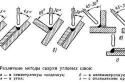
Fillet joints are used when welding various pre-processed sheet edges and are shown in Fig. 11, c. The parts to be welded are located at right angles or other angles and are welded along the edges. Such joints are mainly used for welding tanks operating under low internal pressure of gas or liquid. Sometimes corner joints are also welded from the inside, as shown by the dotted line in Fig. 11, c (left).
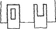
Slotted joints (Fig. 11, d) are used when the length of a normal overlap seam does not provide sufficient
|
|
|
|
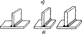
Figure 12 Welded joints: a - end, or side, b - with lining, c - electric rivets //
accurate strength. Slotted joints are either closed or open. The slit is usually oxy-cut.
End, or side, connections are shown in fig. 12, a. The sheets are connected by their surfaces and welded along the adjacent ends.
Connections with straps are shown in fig. 12,
b. Overlay 2, overlapping the joint of sheets 1 and 3, is welded along the side edges to the surface of the sheets. These joints require additional metal consumption for lining and therefore are used only in those cases when for some reason they cannot be replaced with butt or lap joints.
The electrical rivet connection is shown in fig. 12, e. With the help of electric rivets, strong but not tight joints are obtained. The top sheet is drilled and the hole is welded so that the bottom sheet is caught. In automatic submerged arc welding, the top sheet, if its thickness is small, is not pre-drilled and it is melted by the welding arc.
The described joints are typical for manual metal arc welding. In gas welding, submerged arc welding, welding of low-melting non-ferrous metals and in other cases, the shape of the edges may be different. Corresponding information about them will be given in subsequent chapters when describing these welding methods.
Welds are divided into the following groups:
1. By position in space - lower, horizontal, vertical and overhead (Fig. 33, c). The bottom seam is the easiest to perform, and the ceiling seam is the most difficult. Overhead seams can be made by welders who have mastered this type of welding. Execute ceiling seams arc welding harder than gas. Welding horizontal and vertical seams on a vertical surface is somewhat more difficult than welding the bottom seams.
2. In relation to the acting forces - flank, end, or frontal, combined n oblique (Fig. 13, b).
3. By length - continuous, or solid, and discontinuous (Fig. 13, c). Discontinuous seams are used in cases where the joint should not be tight, and according to the strength calculation, a continuous seam is not required.
For an intermittent seam, the length of its individual sections (/) is from 50 to 150 mm; the distance between the sections of the seam is usually 1.5-2.5 times the length of the section; the value of t is called w a - g about the seam. Discontinuous welds are widely used because they provide savings in weld metal, cost and welding time.
4. According to the degree of convexity - normal, convex and concave (Fig. 13, d). Seam bulge a "depends on the type
|
|
a- by position in space, b- in relation to the acting force, c along the length of stn, g- by the degree of convexity of the seam surface
used electrodes: thin-coated electrodes produce a seam with a large convexity; with thick-coated electrodes, due to the greater liquid flow of the molten metal, normal seams are usually obtained.
|
|
Studies have shown that seams with a large bulge do not increase the strength of the seam, especially if the weld is subjected to varying loads and vibrations. This is due to the fact that with seams with a large convexity, it is impossible to obtain a smooth transition from the bead of the seam to the base metal, and in this place a kind of "undercut" of the seam edge is formed, where a significant concentration of stresses occurs.
Therefore, under the action of variable, shock or vibration loads, destruction of the welded joint may begin from this place. Seams with a large convexity are uneconomical, since they require more electrodes, time and energy to complete.
5. By the type of connection - butt and corner (roll
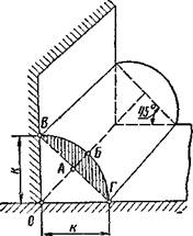
Figure: 14, Corner (roll) seam). Fillet welds apply - "
for lap joints, end-to-end joints, corner joints and joints with overlays. The side to the fillet weld (fig. 14) is the leg. The shaded area AVBG characterizes the degree of weld bulge in comparison with normal and is not taken into account when determining the strength of the welded joint. Fillet welds are made so that their legs are equal, that is, ОВ - ОГ \u003d к. The angle between the sides of the ОГ and ВГ is equal to 45 °.